Infiniti FX35 / FX45. Manual — part 871
PS-26
< SERVICE INFORMATION >
POWER STEERING GEAR AND LINKAGE
a.
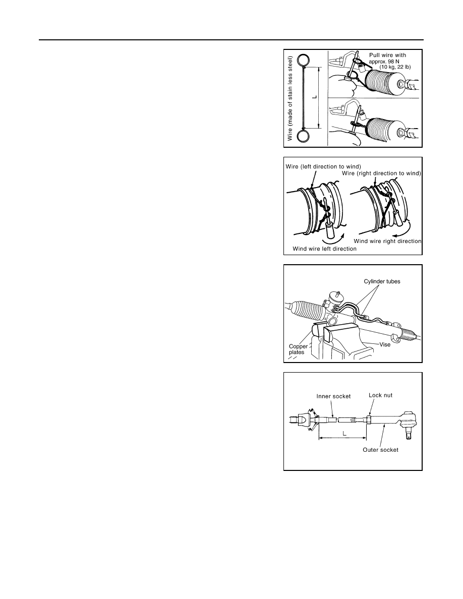
Tighten large-diameter side of RH/LH boot with boot clamp
(stainless wire).
b.
After wrapping clamp around boot groove for two turns, insert
screwdriver in loop on both ends of wire. Twist 4 to 4.5 turns
while pulling with a force of approx. 98 N (10 kg, 22 lb).
c.
Twist boot clamp as shown in the figure, pay attention to rela-
tionship between winding and twisting directions.
22. Install cylinder tubes to gear housing assembly.
23. Install lock nut and outer socket to inner socket.
24. Tighten lightly inner socket in specified length “L”, then tighten
lock nut at specified torque. Refer to "Disassembly and Assem-
bly". Reconfirm if inner socket length is within limit of specified
length “L”.
CAUTION:
Perform toe-in adjustment after this procedure. Length
achieved after toe-in adjustment is not necessary value
given here.
Wire length “L”
: 390 mm (15.35 in)
SGIA0163E
SGIA0164E
SGIA0544E
Inner socket length “L”
: 135.2 mm (5.32 in)
SGIA0167E
POWER STEERING OIL PUMP
PS-27
< SERVICE INFORMATION >
C
D
E
F
H
I
J
K
L
M
A
B
PS
N
O
P
POWER STEERING OIL PUMP
On-Vehicle Inspection and Service
INFOID:0000000001327718
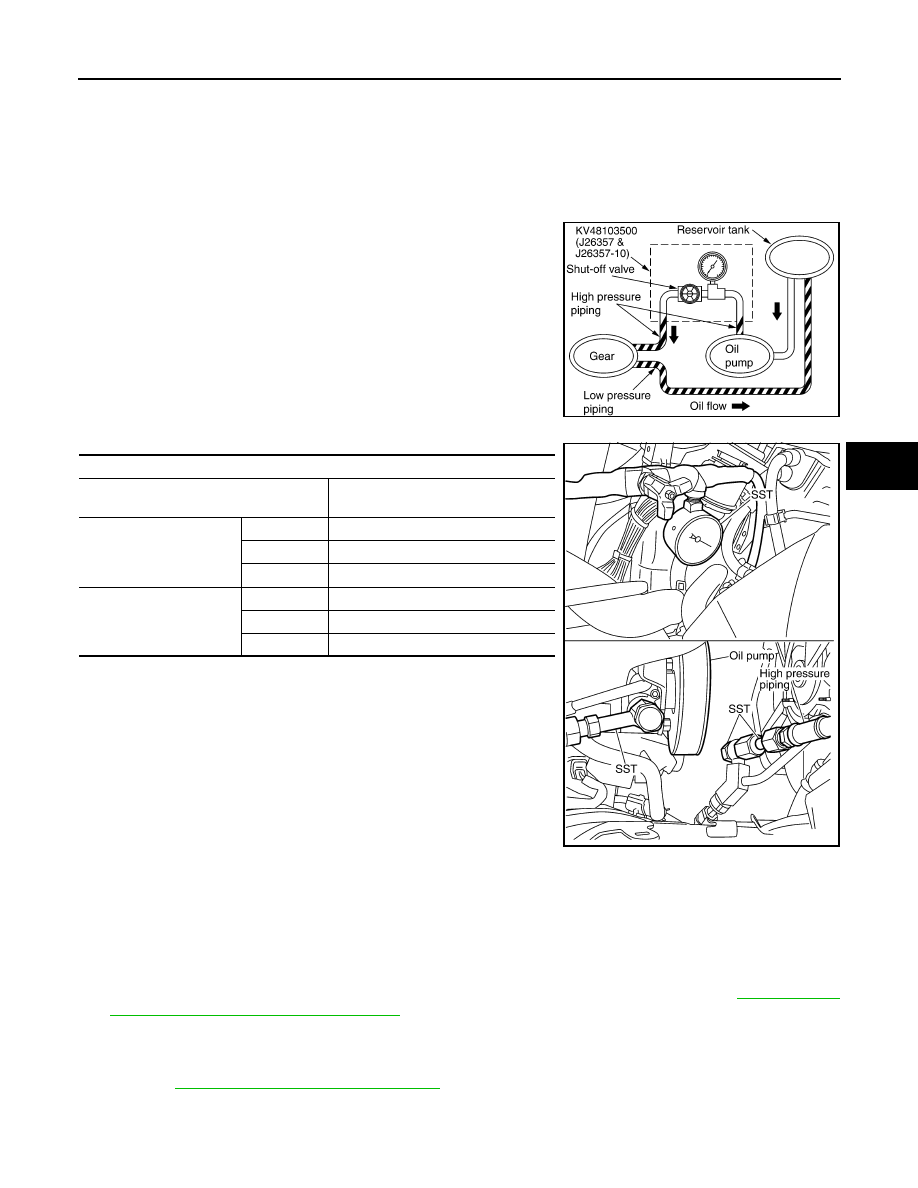
CHECKING RELIEF OIL PRESSURE (VQ35DE MODELS)
CAUTION:
Before starting work, confirm belt tension is proper.
1.
Connect oil pressure gauge (SST) and oil pressure gauge
adapter (SST) between oil pump discharge connector and high
pressure hose and then bleed air from the hydraulic circuit.
2.
Start engine. Allow engine to run until tank temperature reaches
50 to 80
°
C (122 to 176
°
F).
CAUTION:
• Warm up engine with shut-off valve fully opened. If engine
is started with shut-off valve closed, fluid pressure in
power steering pump increases to maximum. This will
raise fluid temperature excessively.
• Be careful not to contact hose with belt when engine is
started.
3.
With engine at idle, close shut-off valve and read the relief oil
pressure.
CAUTION:
Do not close shut-off valve of pressure gauge for more than 10 seconds.
4.
After measurement, open shut-off valve slowly.
If relief oil pressure is outside the specification, disassemble and repair oil pump. Refer to
sembly and Assembly (VQ35DE Models)"
5.
After inspection, disconnect oil pressure gauge (SST) and oil pressure gauge adapter (SST) from hydrau-
lic circuit, connect oil pump discharge connector and high pressure hose. Add fluid and bleed air from
hydraulic circuit thoroughly.
Refer to
PS-7, "Air Bleeding Hydraulic System"
.
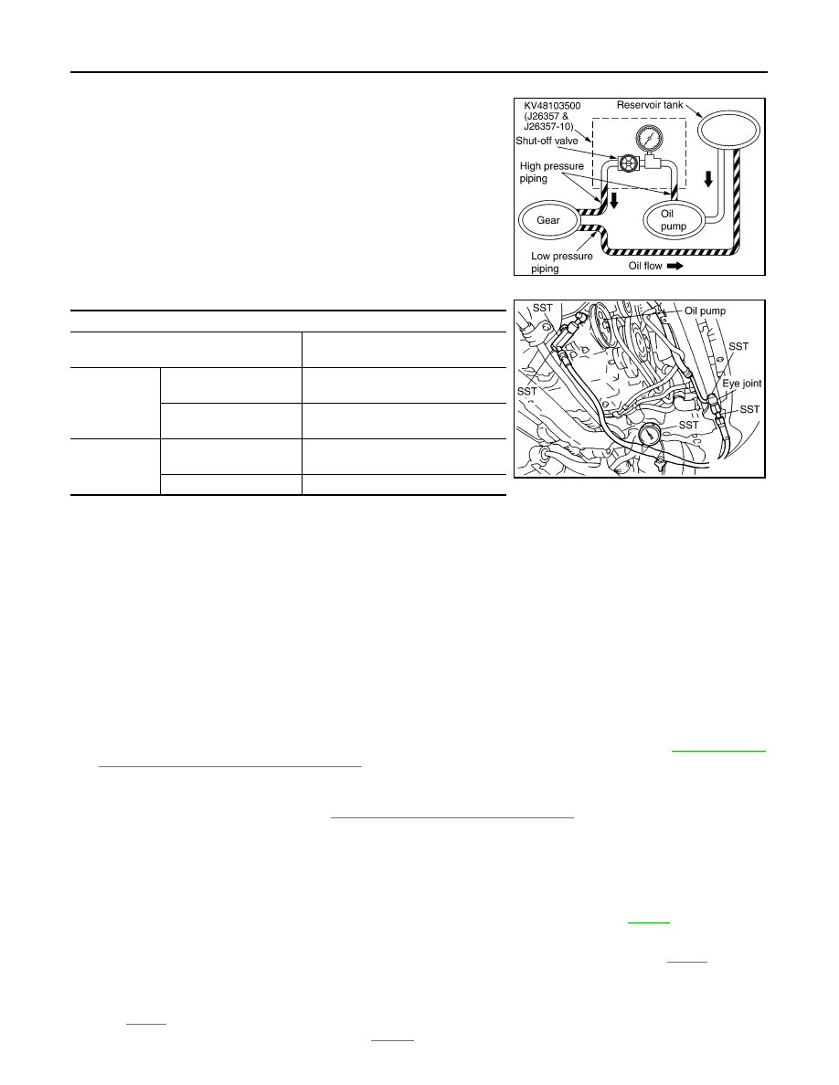
CHECKING RELIEF OIL PRESSURE (VK45DE MODELS)
CAUTION:
SGIA0570E
SST
Pressure gauge
KV48103500
(J-26357&J-26357-10)
Oil pump side
Eye joint
KV48102500-01 ( — )
Washer
KV48102500-04 ( — )
Bolt
KV48102500-03 ( — )
High pressure piping side
Flare joint
KV48102500-02 ( — )
Washer
KV48102500-04 ( — )
Bolt
KV48102500-03 ( — )
Relief oil pressure
: 9,900 - 10,700 kPa (101 - 109.1 kg/cm
2
, 1436 - 1552 psi)
SGIA0522E
PS-28
< SERVICE INFORMATION >
POWER STEERING OIL PUMP
Before starting work, confirm belt tension is proper.
1.
Connect oil pressure gauge (SST) and oil pressure gauge
adapter (SST) between oil pump discharge connector and high
pressure hose and then bleed air from the hydraulic circuit.
2.
Start engine. Allow engine to run until tank temperature reaches 50 to 80
°
C (122 to 176
°
F).
CAUTION:
• Warm up engine with shut-off valve fully opened. If engine is started with shut-off valve closed,
fluid pressure in power steering pump increases to maximum. This will raise fluid temperature
excessively.
• Be careful not to contact hose with belt when engine is started.
3.
With engine at idle, close shut-off valve and read the relief oil pressure.
CAUTION:
Do not close shut-off valve of pressure gauge for more than 10 seconds.
4.
After measurement, open shut-off valve slowly.
If relief oil pressure is outside the specification, disassemble and repair oil pump. Refer to
sembly and Assembly (VK45DE Models)"
.
5.
After inspection, disconnect oil pressure gauge (SST) and oil pressure gauge adapter (SST) from hydrau-
lic circuit, connect oil pump discharge connector and high pressure hose. Add fluid and bleed air from
hydraulic circuit thoroughly. Refer to
PS-7, "Air Bleeding Hydraulic System"
Removal and Installation (VQ35DE Models)
INFOID:0000000001327719
REMOVAL
1.
Remove undercover from vehicle with power tool.
2.
Loosen belt tensioner adjust screw, then remove belt from oil pump pulley. Refer to
.
3.
Drain power steering fluid from reservoir tank.
4.
Remove piping of high pressure and low pressure (drain fluid from their pipings). Refer to
5.
Remove mounting bolts, then remove power steering pump.
INSTALLATION
for tightening torque. Install in the reverse order removal.
• After installation, adjust belt tension. Refer to
SGIA0570E
SST
Pressure gauge and shut-off valve
KV48103500
(J26357 and J26357-10)
Oil pump side
Connector A and O-ring
KV48105300-4 and 5295262U10
(
—
)
Eye-bolt and O-ring
KV48105300-3 and 5295262U00
(
—
)
High pressure
piping side
Connector B and O-ring
KV48105300-1 and 5295262U00
(
—
)
Nut
KV48105300-2
( — )
SGIA0572E
Relief oil pressure
: 9,900 - 10,700 kPa (101 - 109.1 kg/cm
2
, 1436 - 1552 psi)
POWER STEERING OIL PUMP
PS-29
< SERVICE INFORMATION >
C
D
E
F
H
I
J
K
L
M
A
B
PS
N
O
P
• After installation, bleed air. Refer to
PS-7, "Air Bleeding Hydraulic System"
.
Removal and Installation (VK45DE Models)
INFOID:0000000001327720
REMOVAL
1.
Remove undercover from vehicle with power tool.
2.
Remove power steering oil pump belt from auto tensioner. Refer to
3.
Drain power steering fluid from reservoir tank.
4.
Remove piping of high pressure and low pressure from power steering oil pump (drain fluid from their pip-
ings). Refer to
5.
Remove mounting bolts, then remove power steering pump.
INSTALLATION
for tightening torque. Install in the reverse order removal.
After installation, bleed air. Refer to
PS-7, "Air Bleeding Hydraulic System"
.
NOTE:
Adjustment of belt tension is no necessary because engine of this model equips auto tensioner.
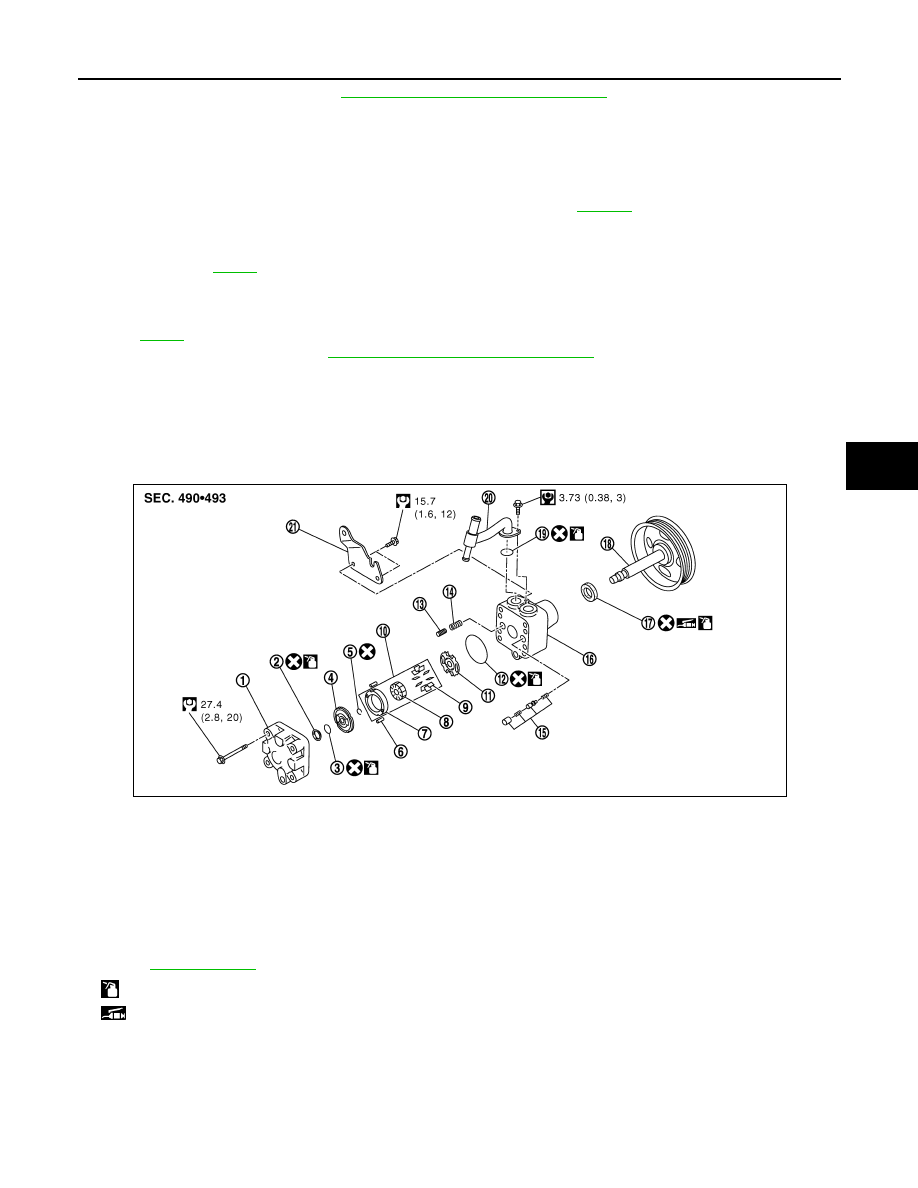
Disassembly and Assembly (VQ35DE Models)
INFOID:0000000001327721
COMPONENTS
INSPECTION BEFORE DISASSEMBLY
Disassemble power steering oil pump only if the following items are found.
• Oil leakage from oil pump
• Deformed or damaged pulley
• Poor performance
1.
Rear cover
2.
Teflon ring
3.
O-ring
4.
Rear side plate
5.
Rotor snap ring
6.
Dowel pin
7.
Cam ring
8.
Rotor
9.
Vane
10. Cartridge
11.
Front side plate
12. O-ring
13. Flow control valve A
14. Spring
15. Flow control valve B assembly
16. Body assembly
17. Oil seal
18. Pulley
19. O-ring
20. Suction pipe
21. Bracket
Refer to
and the followings for the symbols in the figure.
: Apply power steering fluid
: Apply multi-purpose grease
SGIA1679E
Нет комментариевНе стесняйтесь поделиться с нами вашим ценным мнением.
Текст