Infiniti FX35 / FX45. Manual — part 872
PS-30
< SERVICE INFORMATION >
POWER STEERING OIL PUMP
DISASSEMBLY
NOTE:
Fix oil pump in vise as the occasion demands.
CAUTION:
When retaining drive shaft in a vise, always use copper or aluminum plates between vise and shaft.
1.
Unscrew four rear cover bolts and remove rear cover from body assembly.
2.
Remove rear side plate from cartridge, then remove Teflon ring and O-ring from rear side plate.
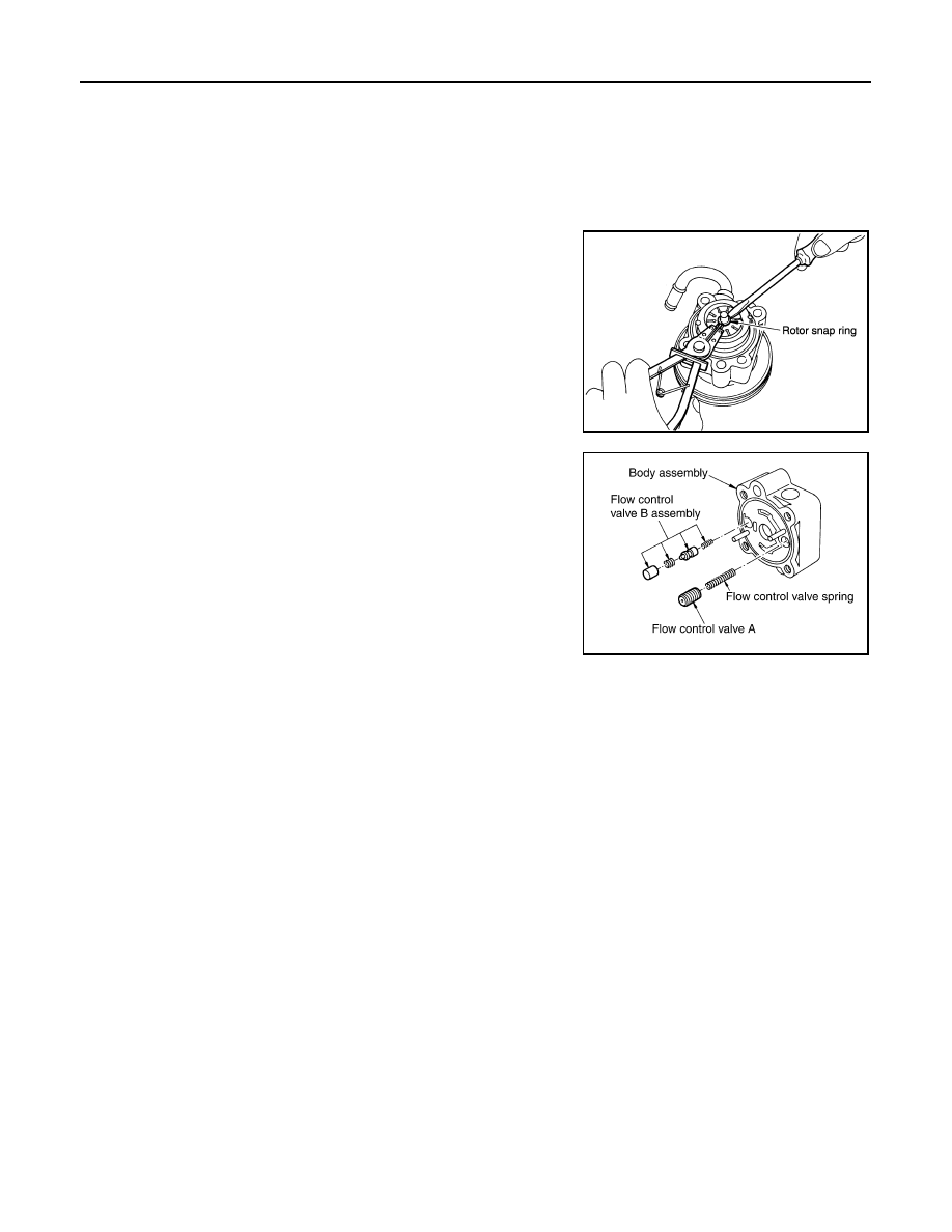
3.
Remove rotor snap ring with snap ring pliers, and remove pulley
from body assembly.
CAUTION:
When removing rotor snap ring, be careful not to damage
pulley shaft.
4.
Remove oil seal from body assembly.
5.
Remove cam ring, rotor, vane, front side plate, flow control valve
A, spring, flow control valve B assembly and O-ring from body
assembly.
CAUTION:
Be careful not to drop and deform flow control valve A and
flow control valve B assembly.
6.
Remove suction pipe from body assembly.
7.
Remove O-ring from suction pipe.
8.
Remove bracket from body assembly.
INSPECTION AFTER DISASSEMBLY
Body Assembly and Rear Cover Inspection
Check body assembly and rear cover for internal damage. Replace rear cover if it is damaged. Replace oil
pump assembly if body assembly is damaged.
Cartridge Assembly Inspection
Check cam ring, rotor and vane for damage. Replace cartridge assembly if necessary.
Side Plate Inspection
Check side plate (front and rear) for damage. Side plate (front and rear) must be replaced as a set if they are
damaged.
Flow Control Valve Inspection
Check flow control valve A, flow control valve spring and flow control valve B assembly for damage. Replace if
there are.
ASSEMBLY
NOTE:
Fix oil pump in vise as occasion demands.
CAUTION:
When retaining drive shaft in a vise, always use copper or aluminum plates between vise and shaft.
SGIA0059E
SGIA0526E
POWER STEERING OIL PUMP
PS-31
< SERVICE INFORMATION >
C
D
E
F
H
I
J
K
L
M
A
B
PS
N
O
P
1.
Apply recommended grease to oil seal lips. Apply recommended
fluid to around oil seal, and then install oil seal to body assembly
using the drift [SST].
2.
If dowel pin has been removed, insert it into body assembly by
hand. If it cannot be inserted by hand, lightly tap with a hammer.
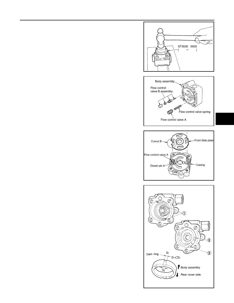
3.
Install flow control valve A, flow control valve spring and flow
control valve B assembly to locations shown in the figure.
4.
Match dowel pin A on flow control valve A, shown in the figure,
with cutout B of front side plate and then install front side plate to
body assembly.
5.
Install cam ring onto front side plate with smaller slit of cam ring
facing body assembly.
6.
Install pulley to body assembly.
CAUTION:
When installing pulley, be careful not to scratch oil seal.
SGIA0527E
SGIA0526E
SGIA0528E
SGIA0623E
PS-32
< SERVICE INFORMATION >
POWER STEERING OIL PUMP
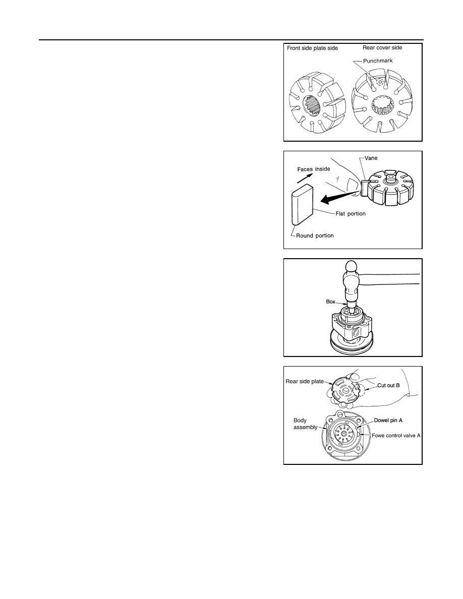
7.
Face the side of rotor with punch mark towards rear cover, and
attach rotor to pulley shaft.
8.
Install vane to rotor with facing the round portion outside.
9.
Using a hammer and a 10 mm (0.39 in) box, install rotor snap
ring to slot in pulley shaft.
CAUTION:
Be careful not to damage rotor and pulley shaft.
10. Match dowel pin A on flow control valve A, shown in the figure,
with cutout B of rear side plate and install rear side plate to car-
tridge.
11. Apply recommended fluid to O-ring and install O-ring into rear
side plate.
12. Apply recommended fluid to Teflon ring and Install Teflon ring
into rear side plate.
13. Position rear cover on body assembly and tighten mounting
bolts to specified torque.
14. Apply recommended fluid to O-ring and install O-ring into suc-
tion pipe.
15. Install suction pipe into body assembly.
16. Install bracket to body assembly and tighten mounting bolts to specified torque.
Disassembly and Assembly (VK45DE Models)
INFOID:0000000001327722
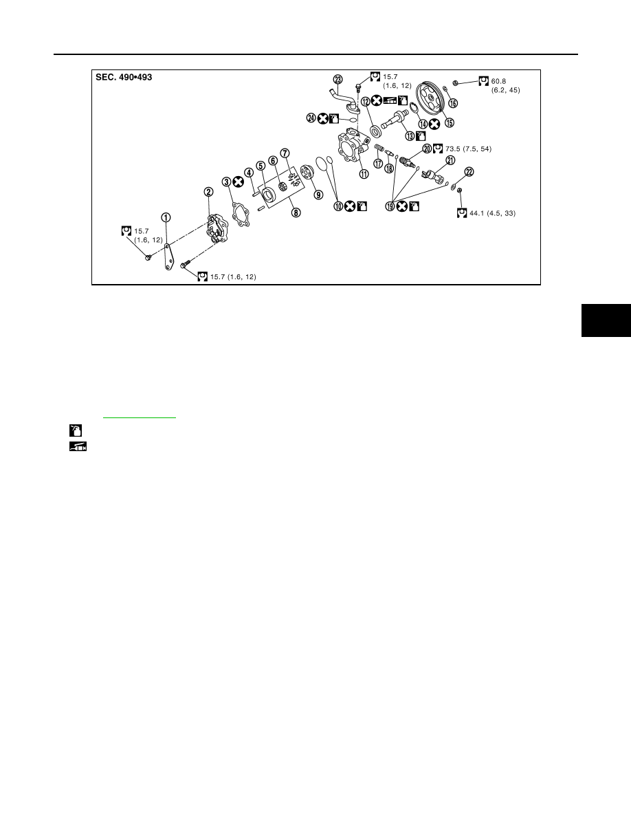
COMPONENTS
SGIA0529E
SST843A
SGIA0063E
SGIA0530E
POWER STEERING OIL PUMP
PS-33
< SERVICE INFORMATION >
C
D
E
F
H
I
J
K
L
M
A
B
PS
N
O
P
INSPECTION BEFORE DISASSEMBLY
Disassemble power steering oil pump only if the following items are found.
• Oil leakage from oil pump.
• Deformed or damaged pulley
• Poor performance
DISASSEMBLY
NOTE:
Fix oil pump in vise as the occasion demands.
CAUTION:
When retaining drive shaft in a vise, always use copper or aluminum plates between vise and shaft.
1.
Unscrew three bracket bolts and remove bracket from rear cover.
2.
Unscrew four rear cover bolts and remove rear cover from body assembly.
3.
Remove gasket from body assembly.
4.
Remove lock pin, cartridge and side plate from body assembly.
5.
Remove pulley from drive shaft assembly.
1.
Bracket
2.
Rear cover
3.
Gasket
4.
Lock pin
5.
Cam ring
6.
Rotor
7.
Vane
8.
Cartridge
9.
Side plate
10. O-ring
11.
Body assembly
12. Oil seal
13. Drive shaft assembly
14. Snap ring
15. Pulley
16. Spring washer
17. Spring
18. Flow control valve
19. O-ring
20. Connector bolt
21. Joint
22. Washer
23. Suction pipe
24. O-ring
Refer to
and the followings for the symbols in the figure.
: Apply power steering fluid
: Apply multi-purpose grease
SGIA1680E
Нет комментариевНе стесняйтесь поделиться с нами вашим ценным мнением.
Текст