Infiniti FX35 / FX45. Manual — part 388
DTC P0300, P0301, P0302, P0303, P0304, P0305, P0306 MULTIPLE CYLINDER
MISFIRE, NO. 1 - 6 CYLINDER MISFIRE
EC-313
< SERVICE INFORMATION >
[VQ35DE]
C
D
E
F
G
H
I
J
K
L
M
A
EC
N
P
O
NG
>> Follow the
14.
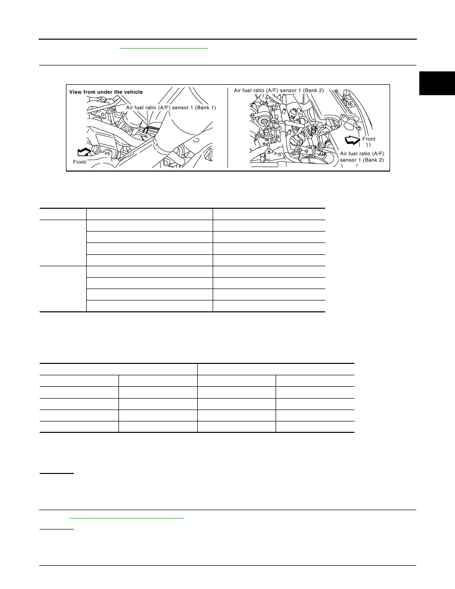
CHECK AIR FUEL RATIO (A/F) SENSOR 1 INPUT SIGNAL
1.
Turn ignition switch OFF.
2.
Disconnect A/F sensor 1 harness connector.
3.
Disconnect ECM harness connector.
4.
Check harness continuity between the following terminals.
Refer to Wiring Diagram.
5.
Check harness continuity between the following terminals and ground.
Refer to Wiring Diagram.
6.
Also check harness for short to power or short to ground.
OK or NG
OK
>> GO TO 15.
NG
>> Repair open circuit or short to ground or short to power in harness or connectors.
15.
CHECK AIR FUEL RATIO (A/F) SENSOR 1 HEATER
EC-158, "Component Inspection"
OK or NG
OK
>> GO TO 16.
NG
>> Replace malfunctioning air fuel ratio (A/F) sensor 1.
16.
CHECK MASS AIR FLOW SENSOR
A/F sensor 1 terminal
ECM terminal
Bank 1
1
16
2
75
5
35
6
56
Bank 2
1
76
2
77
5
57
6
58
Continuity should exist.
Bank 1
Bank 2
A/F sensor 1 terminal
ECM terminal
A/F sensor 1 terminal
ECM terminal
1
16
1
76
2
75
2
77
5
35
5
57
6
56
6
58
Continuity should not exist.
PBIB2093E

EC-314
< SERVICE INFORMATION >
[VQ35DE]
DTC P0300, P0301, P0302, P0303, P0304, P0305, P0306 MULTIPLE CYLINDER
MISFIRE, NO. 1 - 6 CYLINDER MISFIRE
With CONSULT-III
Check mass air flow sensor signal in “DATA MONITOR” mode with CONSULT-III.
With GST
Check mass air flow sensor signal in Service $01 with GST.
OK or NG
OK
>> GO TO 17.
NG
>> Check connectors for rusted terminals or loose connections in the mass air flow sensor circuit or
ground. Refer to
.
17.
CHECK SYMPTOM MATRIX CHART
Check items on the rough idle symptom in
.
OK or NG
OK
>> GO TO 18.
NG
>> Repair or replace.
18.
ERASE 1ST TRIP DTC
Some tests may cause a 1st trip DTC to be set.
Erase the 1st trip DTC from the ECM memory after performing the tests. Refer to
.
>> GO TO 19.
19.
CHECK INTERMITTENT INCIDENT
>> INSPECTION END
2.0 - 6.0 g·m/sec:
at idling
7.0 - 20.0 g·m/sec:
at 2,500 rpm
2.0 - 6.0 g·m/sec:
at idling
7.0 - 20.0 g·m/sec:
at 2,500 rpm
DTC P0327, P0328 KS
EC-315
< SERVICE INFORMATION >
[VQ35DE]
C
D
E
F
G
H
I
J
K
L
M
A
EC
N
P
O
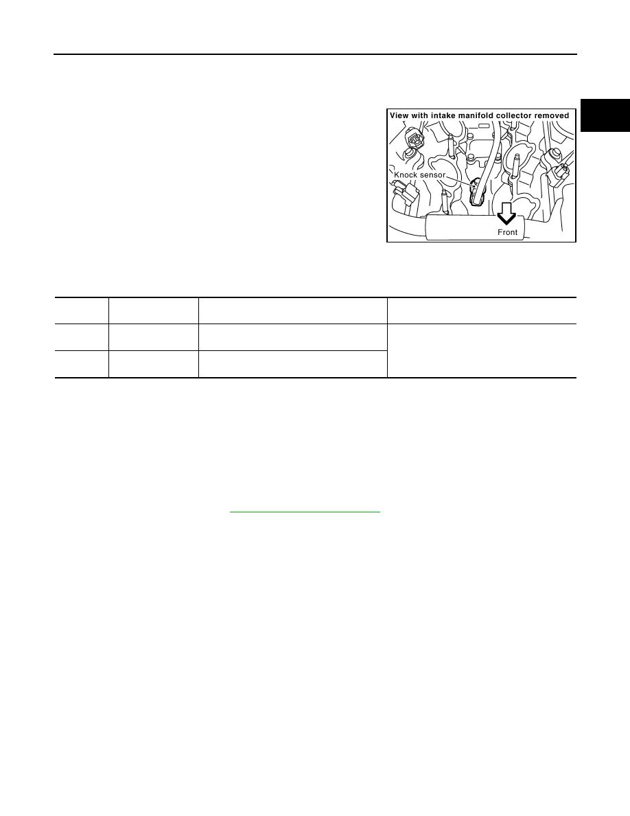
DTC P0327, P0328 KS
Component Description
INFOID:0000000001326134
The knock sensor (KS) is attached to the cylinder block. It senses
engine knocking using a piezoelectric element. A knocking vibration
from the cylinder block is sensed as vibrational pressure. This pres-
sure is converted into a voltage signal and sent to the ECM.
On Board Diagnosis Logic
INFOID:0000000001326135
The MIL will not light up for these self-diagnoses.
DTC Confirmation Procedure
INFOID:0000000001326136
NOTE:
If DTC Confirmation Procedure has been previously conducted, always turn ignition switch OFF and wait at
least 10 seconds before conducting the next test.
TESTING CONDITION:
Before performing the following procedure, confirm that battery voltage is more than 10V at idle.
1.
Start engine and run it for at least 5 seconds at idle speed.
2.
Check 1st trip DTC.
3.
If 1st trip DTC is detected, go to
PBIB1564E
DTC No.
Trouble diagnosis
name
DTC detected condition
Possible cause
P0327
0327
Knock sensor circuit
low input
An excessively low voltage from the sensor is
sent to ECM.
• Harness or connectors
(Knock sensor circuit is open or shorted.)
• Knock sensor
P0328
0328
Knock sensor circuit
high input
An excessively high voltage from the sensor is
sent to ECM.
EC-316
< SERVICE INFORMATION >
[VQ35DE]
DTC P0327, P0328 KS
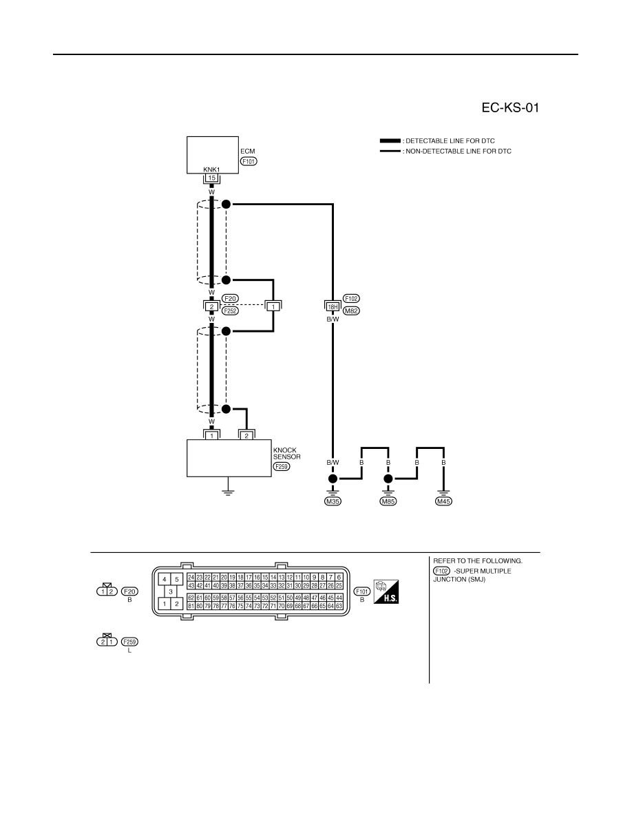
Wiring Diagram
INFOID:0000000001326137
Specification data are reference values and are measured between each terminal and ground.
CAUTION:
Do not use ECM ground terminals when measuring input/output voltage. Doing so may result in dam-
age to the ECM's transistor. Use a ground other than ECM terminals, such as the ground.
TBWM0296E
Нет комментариевНе стесняйтесь поделиться с нами вашим ценным мнением.
Текст