Infiniti FX35 / FX45. Manual — part 164
AV-110
< SERVICE INFORMATION >
NAVIGATION SYSTEM
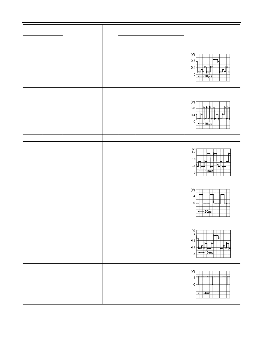
46 (R)
Ground
RGB signal (G: green)
Input
ON
Start Confirmation/Adjust-
ment (Navigation) mode,
and then display color bar by
selecting “Color Spectrum
bar” on Display Diagnosis
screen
47
—
Shield
—
—
—
—
48 (B)
Ground
RGB signal (B: blue)
Input
ON
Start Confirmation/Adjust-
ment (Navigation) mode,
and then display color bar by
selecting “Color Spectrum
bar” on Display Diagnosis
screen
49
—
Shield
—
—
—
—
50 (G)
Ground
RGB signal (R: red)
Output
ON
Start Confirmation/Adjust-
ment mode, and then dis-
play color bar by selecting
“Display Color Spectrum
Bar” on Display Diagnosis
screen
51 (B)
Ground
RGB area (YS) signal
Output
ON
Set the selector lever in R
position, and then display
the rear view image
52 (Y)
Ground
RGB signal (G: green)
Output
ON
Start Confirmation/Adjust-
ment mode, and then dis-
play color bar by selecting
“Display Color Spectrum
Bar” on Display Diagnosis
screen
53 (W)
Ground
Vertical
synchronizing (VP)
signal
Input
ON
—
Terminal
(Wire color)
Item
Signal
input/
output
Condition
Reference value
+
–
Ignition
switch
Operation
SKIB7361E
SKIB7362E
SKIB7769E
SKIB3599E
SKIB7770E
SKIB3598E
NAVIGATION SYSTEM
AV-111
< SERVICE INFORMATION >
C
D
E
F
G
H
I
J
L
M
A
B
AV
N
O
P
Terminal and Reference Value for Display
INFOID:0000000001328749
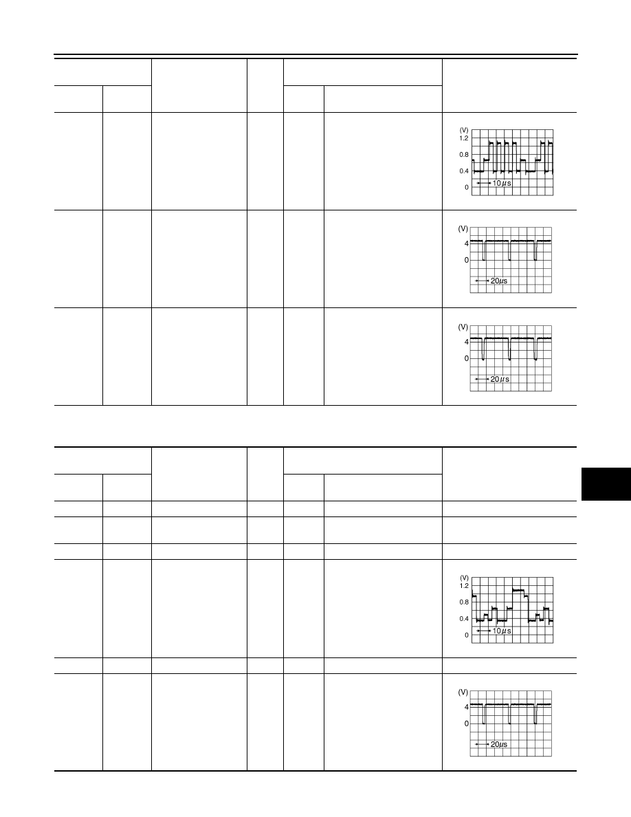
54 (L)
Ground
RGB signal (B: blue)
Output
ON
Start Confirmation/Adjust-
ment mode, and then dis-
play color bar by selecting
“Display Color Spectrum
Bar” on Display Diagnosis
screen
55 (R)
Ground
Horizontal
synchronizing (HP)
signal
Input
ON
—
56 (G)
Ground
RGB synchronizing
signal
Output
ON
When displaying RGB im-
age
Terminal
(Wire color)
Item
Signal
input/
output
Condition
Reference value
+
–
Ignition
switch
Operation
SKIB7771E
SKIB3601E
SKIB3603E
Terminal
(Wire color)
Item
Signal
input/
output
Condition
Reference value
+
–
Ignition
switch
Operation
1 (B)
Ground
Ground
—
ON
—
Approx. 0 V
2 (W/G)
Ground
Power supply (Invert-
er)
Input
ON
—
Approx. 9 V
3 (BR/W)
Ground
Power supply (Signal)
Input
ON
—
Approx. 9 V
6 (Y)
Ground
RGB signal (G: green)
Input
ON
Start Confirmation/Adjust-
ment mode, and then dis-
play color bar by selecting
“Display Color Spectrum
Bar” on Display Diagnosis
screen
7
—
Shield
—
—
—
—
8 (R)
Ground
Horizontal
synchronizing (HP)
signal
Output
ON
—
SKIB7770E
SKIB3601E
AV-112
< SERVICE INFORMATION >
NAVIGATION SYSTEM
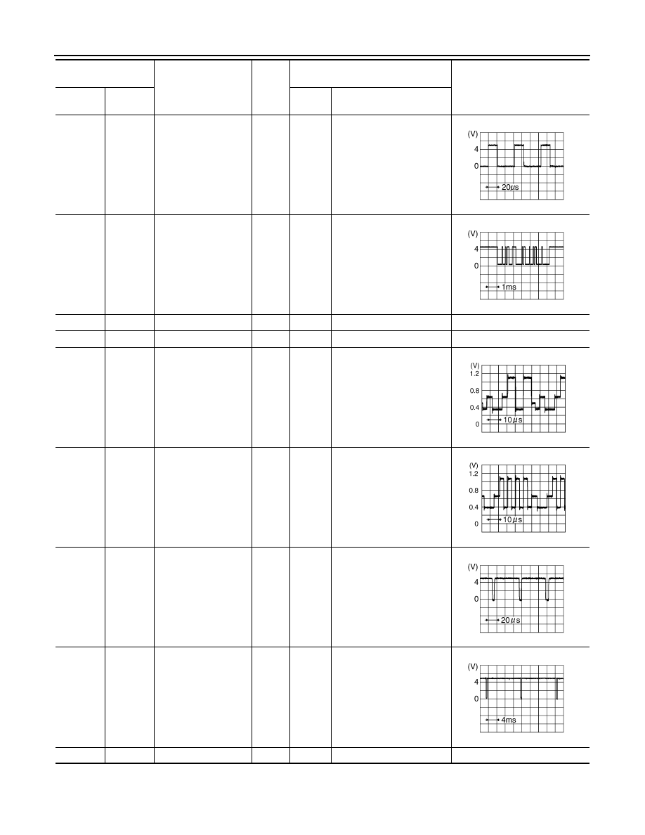
9 (B)
Ground
RGB area (YS) signal
Input
ON
Set the selector lever in R
position, and then display
the rear view image
11 (PU)
Ground
Communication signal
(DCU-DSP)
Input
ON
—
13 (P)
Ground
Ground (Inverter)
—
ON
—
Approx. 0 V
14 (P/L)
Ground
Ground (Signal)
—
ON
—
Approx. 0 V
17 (G)
Ground
RGB signal (R: red)
Input
ON
Start Confirmation/Adjust-
ment mode, and then dis-
play color bar by selecting
“Display Color Spectrum
Bar” on Display Diagnosis
screen
18 (L)
Ground
RGB signal (B: blue)
Input
ON
Start Confirmation/Adjust-
ment mode, and then dis-
play color bar by selecting
“Display Color Spectrum
Bar” on Display Diagnosis
screen
19 (G)
Ground
RGB synchronizing
signal
Input
ON
When displaying RGB im-
age
20 (W)
Ground
Vertical
synchronizing (VP)
signal
Output
ON
—
21
—
Shield
—
—
—
—
Terminal
(Wire color)
Item
Signal
input/
output
Condition
Reference value
+
–
Ignition
switch
Operation
SKIB3599E
SKIB3607E
SKIB7769E
SKIB7771E
SKIB3603E
SKIB3598E

NAVIGATION SYSTEM
AV-113
< SERVICE INFORMATION >
C
D
E
F
G
H
I
J
L
M
A
B
AV
N
O
P
Terminal and Reference Value for A/C and AV Switch
INFOID:0000000001328750
Special Note for Trouble Diagnosis
INFOID:0000000001328751
Prior to performing trouble diagnosis, make sure there are no corresponding description in the “Example of
Symptoms Possible No Malfunction”. Refer to
AV-138, "Example of Symptom Possible No Malfunction"
.
On Board Self-Diagnosis Function
INFOID:0000000001328752
DESCRIPTION
• Trouble diagnosis function of navigation system has a Self Diagnosis mode by automatic operation and a
Confirmation/Adjustment mode by manual operation.
• Self Diagnosis mode checks for connections between the units constituting this system, analyzes each indi-
vidual unit at the same time, and displays the results on the display.
• Confirmation/Adjustment mode displays trouble diagnosis that require an operation and a judgment by a
human (auto-decision cannot be performed by the system), confirmation of preset value, and an error his-
tory.
DIAGNOSIS ITEM
22 (LG)
Ground
Communication signal
(DSP-DCU)
Output
ON
—
23
—
Shield
—
—
—
—
Terminal
(Wire color)
Item
Signal
input/
output
Condition
Reference value
+
–
Ignition
switch
Operation
SKIB3606E
Terminal
(Wire color)
Item
Signal
input/
output
Condition
Reference value
+
–
Ignition
switch
Operation
1 (W/L)
Ground
Battery power supply
Input
OFF
—
Battery voltage
2 (LG)
Ground
ACC power supply
Input
ACC
—
Battery voltage
5 (B)
Ground
Ground
—
ON
—
Approx. 0 V
6 (PU)
Ground
Communication
signal (+)
Input/
Output
ON
—
7
—
Shield
—
—
—
—
8 (LG)
Ground
Communication
signal (–)
Input/
Output
ON
—
SKIB7378E
SKIB7379E
Нет комментариевНе стесняйтесь поделиться с нами вашим ценным мнением.
Текст