Infiniti FX35 / FX45. Manual — part 165
AV-114
< SERVICE INFORMATION >
NAVIGATION SYSTEM
Self-Diagnosis Mode (DCU)
INFOID:0000000001328753
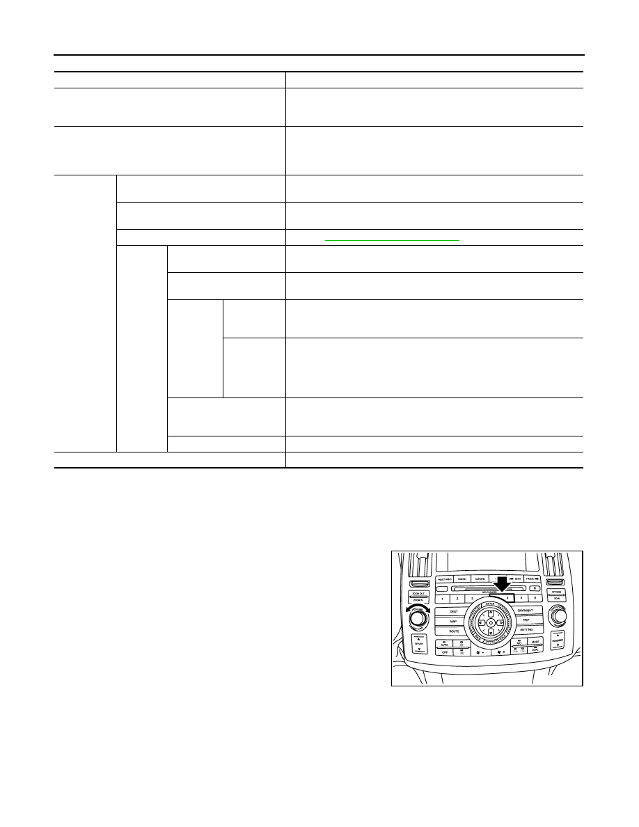
OPERATION PROCEDURE
1.
Start the engine.
2.
Turn the audio system OFF.
3.
While pressing the “4” button, turn the volume control dial clock-
wise or counterclockwise for 30 clicks or more. (When the self-
diagnosis mode is started, a short beep will be heard.)
• Shifting from current screen to previous screen is performed
by pressing “BACK” button.
Mode
Description
Self Diagnosis (DCU)
• Display control unit diagnosis
• Analyzes connection between the display control unit and each unit, and
operation of each unit.
Self Diagnosis (NAVI)
• NAVI control unit diagnosis (DVD-ROM drive will not be diagnosed when
no DVD-ROM is in it.).
• Analyzes connection between the NAVI control unit and the GPS anten-
na.
Confirmation/
Adjustment
Display Diagnosis
Color tone and shading of the display control unit-generated image can be
checked by the display of a color bar and a gray scale.
Vehicle Signals
Diagnosis of signals that are input to display control unit can be performed
for Vehicle Speed, IGN, Reverse and Light.
Auto Climate Control
Refer to
ATC-43, "Self-Diagnosis Function"
.
Navigation
Display Diagnosis
Color tone and shading of the NAVI control unit-generated image can be
checked by the display of a color bar and a gray scale.
Vehicle Signals
Diagnosis of signals that are input to NAVI control unit can be performed for
Vehicle speed, Lights, Ignition and Reverse.
Navigation
Steering An-
gle
Adjustment
This mode is used to correct difference between actual turning angle of a
vehicle and turning angle of the vehicle mark on the display.
Speed
Calibration
Under ordinary conditions, the navigation system distance measuring func-
tion will automatically compensate for minute decreases in wheel and tire
diameter caused by tire wear or low-pressure. Speed Calibration can im-
mediately restore system accuracy in cases such as when distance calibra-
tion is needed because of the use of tire chains.
Error History
Malfunctions that occurred in the past are displayed, along with the number
of times each has occurred. Time and location when/where the errors oc-
curred are also displayed.
Delete Unit Connection Log
Erase the connection history of unit and error history.
CAN DIAG SUPPOPT MONITOR
The transmitting/receiving of CAN communication can be monitored.
SKIB8642E
NAVIGATION SYSTEM
AV-115
< SERVICE INFORMATION >
C
D
E
F
G
H
I
J
L
M
A
B
AV
N
O
P
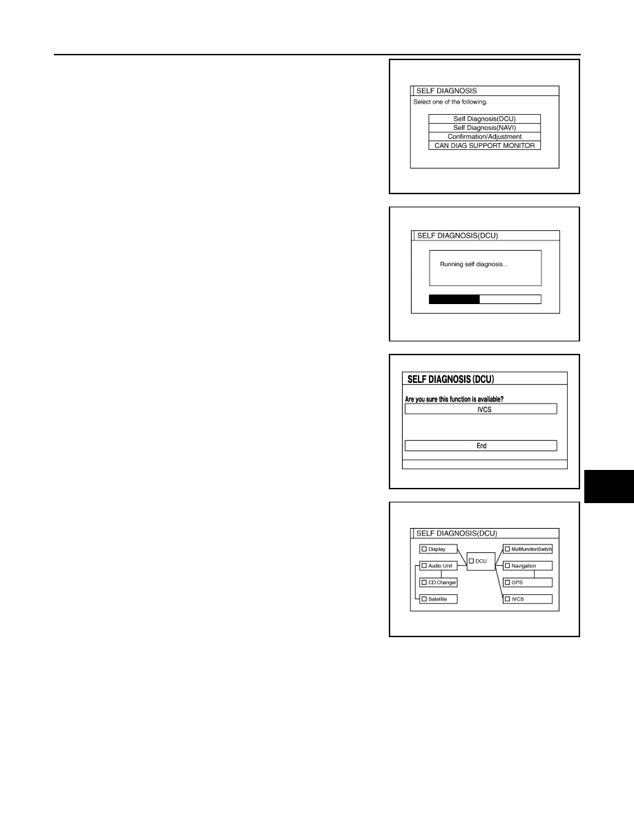
4.
The initial trouble diagnosis screen will be shown, and items
“Self Diagnosis (DCU)”, “Self Diagnosis (NAVI)”, “Confirmation/
Adjustment” and “CAN DIAG SUPPORT MONITOR” will
become selective.
5.
Perform self-diagnosis by selecting the “Self Diagnosis (DCU)”.
• Self-diagnosis screen is displayed, and then self-diagnosis
starts.
• The bar graph visible below self-diagnosis screen displays
progress of the diagnosis.
6.
When the self-diagnosis completes, optional part confirmation
screen will be shown.
• When connection of an optional part is judged error, a screen
to check if the optional part is actually fitted on the vehicle or
not will be shown. When fitted, select the switch of the part on
the screen and press “End”. Then the “SELF DIAGNOSIS”
screen will be shown.
• When the optional part is connected normally, the switch for
the part will not appear on the screen.
7.
On the diagnosis results screen, each unit name and connection
line will be colored according to the diagnosis result, as follows.
NOTE:
• Satellite = Satellite radio tuner
• DCU = Display control unit
• Multifunction switch = A/C and AV switch
• Navigation = NAVI control unit
• GPS = GPS antenna
• If multiple malfunctions occur at the same time for a single unit, the screen switch colors are determined
according to the following order of priority: red > yellow > gray.
SKIB7874E
SKIA4208E
SKIB8673E
Green
: No malfunctioning.
Gray
: Cannot be judged by self-diagnosis results.
Red
: Unit is malfunctioning.
SKIB7875E
AV-116
< SERVICE INFORMATION >
NAVIGATION SYSTEM
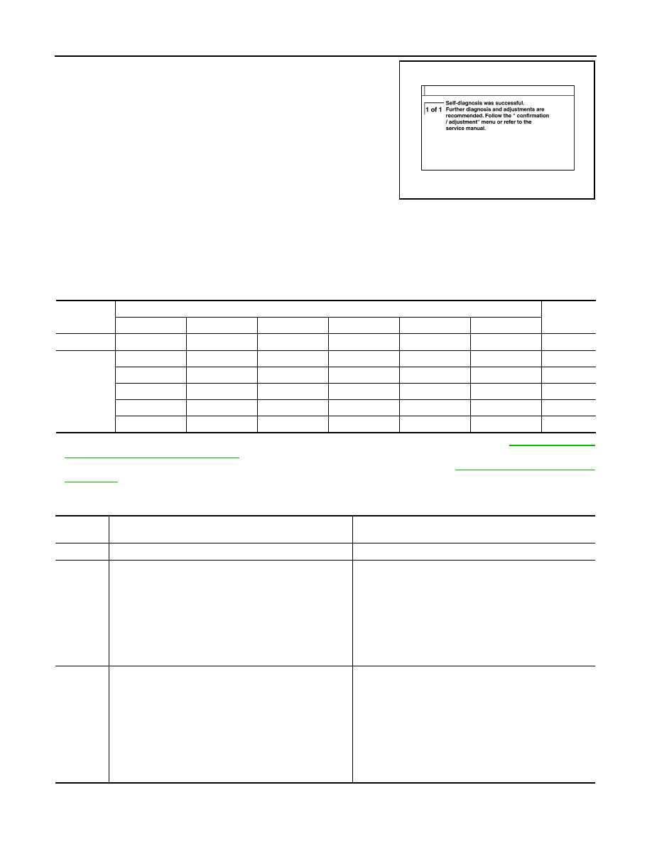
8.
Select a switch on the diagnosis results screen, and comments
for the diagnosis results will be shown.
SELF-DIAGNOSIS RESULT
Quick Reference Table
1.
Select the applicable diagnosis number in the quick reference table of diagnosis result.
2.
Confirm the possible malfunction with the diagnosis table, and then perform inspection.
3.
Turn ignition switch OFF and perform self-diagnosis again.
• When A/C and AV switch has a malfunction, the self-diagnosis cannot be started. Refer to
AV Switch Self-Diagnosis Function"
.
• When display has a malfunction, the self-diagnosis cannot be started. Refer to
Self-Diagnosis Codes
SKIA4211E
Switch color
Screen switch
Diagnosis
No.
DCU
Display
Audio Unit
Navigation
GPS
Satellite
Red
×
1
Gray
×
2
×
×
3
×
×
4
×
5
×
6
Diagnosis
No.
Possible cause
Action to take
1
Display control unit malfunction is detected.
Replace display control unit.
2
Malfunction is detected on communication signal between
display control unit and display.
1.
Check communication circuit between display control
unit and display.
2.
Check communication signal between display control
unit and display.
3.
If the results from the above checkup show no mal-
function, replace either display control unit or display,
and then start self-diagnosis.
4.
If self-diagnosis results still show any malfunction, re-
place the other unit.
3
• Audio unit power supply circuit malfunction is detected.
• Malfunction is detected on communication signal be-
tween display control unit and audio unit.
1.
Check audio unit power supply circuit.
2.
Check communication circuit between display control
unit and audio unit.
3.
Check communication signal between display control
unit and audio unit.
4.
If the results from the above checkup show no mal-
function, replace either display control unit or audio
unit, and then start self-diagnosis.
5.
If self-diagnosis results still show any malfunction, re-
place the other unit.
NAVIGATION SYSTEM
AV-117
< SERVICE INFORMATION >
C
D
E
F
G
H
I
J
L
M
A
B
AV
N
O
P
Self-Diagnosis Mode (NAVI)
INFOID:0000000001328754
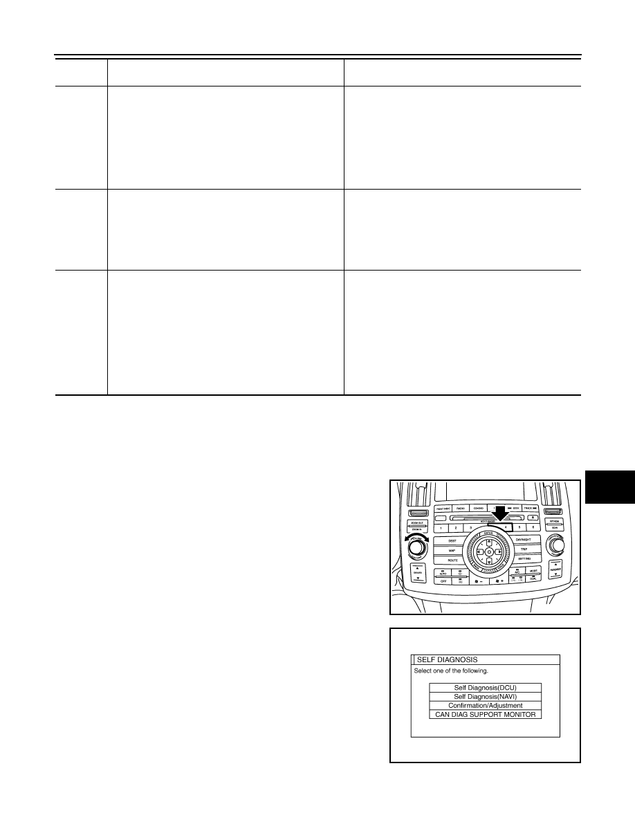
OPERATION PROCEDURE
1.
Start the engine.
2.
Turn the audio system OFF.
3.
While pressing the “4” button, turn the volume control dial clock-
wise or counterclockwise for 30 clicks or more. (When the self-
diagnosis mode is started, a short beep will be heard.)
• Shifting from current screen to previous screen is performed
by pressing “BACK” button.
4.
The initial trouble diagnosis screen will be shown, and items
“Self Diagnosis (DCU)”, “Self Diagnosis (NAVI)”, “Confirmation/
Adjustment” and “CAN DIAG SUPPORT MONITOR” will
become selective.
NOTE:
Select “Self Diagnosis (DCU)” when “Self Diagnosis (NAVI)” is
not available. Repair malfunctioning part.
4
• NAVI control unit power supply and ground circuit mal-
function is detected.
• Malfunction is detected on communication signal be-
tween display control unit and NAVI control unit.
1.
Check NAVI control unit power supply and ground cir-
cuit.
2.
Check communication circuit between display control
unit and NAVI control unit.
3.
If the results from the above checkup show no mal-
function, replace either display control unit or NAVI
control unit, and then start self-diagnosis.
4.
If self-diagnosis results still show any malfunction, re-
place the other unit.
5
GPS antenna connection malfunction is detected.
1.
Check if GPS antenna feeder line is snapped or
pinched.
2.
If the results from the above checkup show no mal-
function, replace GPS antenna, and then restart self-
diagnosis.
3.
If self-diagnosis results still show any malfunction, re-
place NAVI control unit.
6
• Satellite radio tuner power supply and ground circuit mal-
function is detected.
• Malfunction is detected on communication signal be-
tween audio unit and satellite radio tuner.
1.
Check satellite radio tuner power supply and ground
circuit.
2.
Check communication circuit between audio unit and
satellite radio tuner.
3.
Check communication signal between audio unit and
satellite radio tuner.
4.
If the results from the above checkup show no mal-
function, replace either audio unit or satellite radio tun-
er, and then start self-diagnosis.
5.
If self-diagnosis results still show any malfunction, re-
place the other unit.
Diagnosis
No.
Possible cause
Action to take
SKIB8642E
SKIB7874E
Нет комментариевНе стесняйтесь поделиться с нами вашим ценным мнением.
Текст