Infiniti FX35 / FX45. Manual — part 288
UNIFIED METER AND A/C AMP
DI-27
< SERVICE INFORMATION >
C
D
E
F
G
H
I
J
L
M
A
B
DI
N
O
P
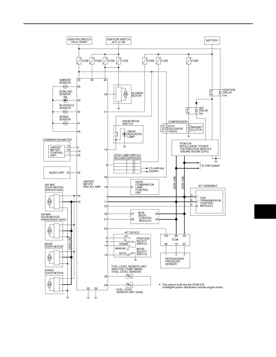
Schematic
INFOID:0000000001328457
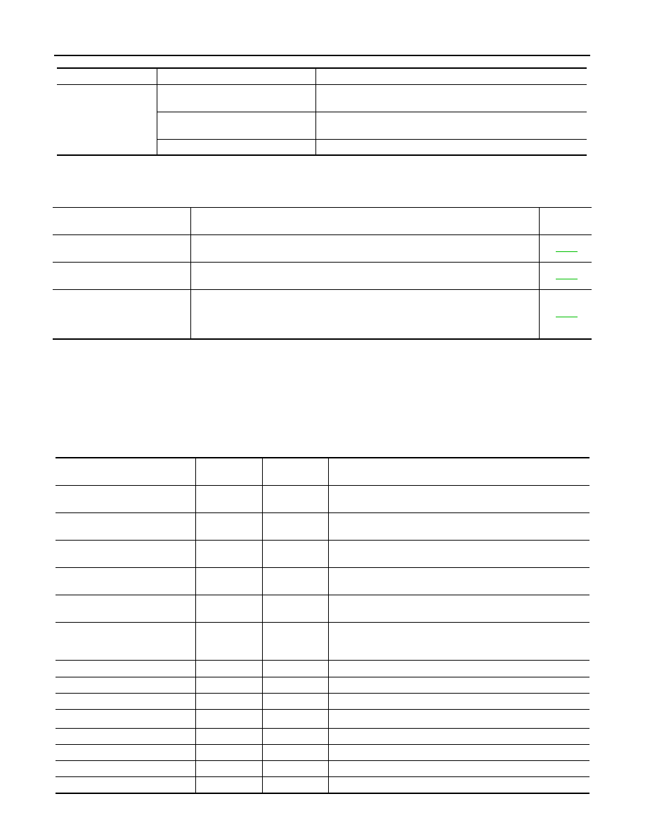
CONSULT-III Function (METER/M&A)
INFOID:0000000001328458
CONSULT-III can display each diagnostic item using the diagnostic test modes shown following.
TKWM4365E
DI-28
< SERVICE INFORMATION >
UNIFIED METER AND A/C AMP
SELF-DIAG RESULTS
Display Item List
NOTE:
“TIME” means the following.
• 0: Means detected malfunction at present. (From malfunction detection to turning ignition switch OFF)
• 1 - 63: Means detected malfunction in the past. (Displays the number of ignition switch OFF
→
ON after
detecting malfunction. “Self Diagnostic Result” is erased when exceeding “63”.)
DATA MONITOR
Display Item List
X: Applicable
System
Diagnosis mode
Description
METER A/C AMP
Self Diagnostic Result
Unified meter and A/C amp. checks the conditions and displays
memorized error.
CAN DIAG SUPPORT MNTR
The results of transmit/receive diagnosis of CAN communication
can be read.
Data Monitor
Displays unified meter and A/C amp. input data in real time.
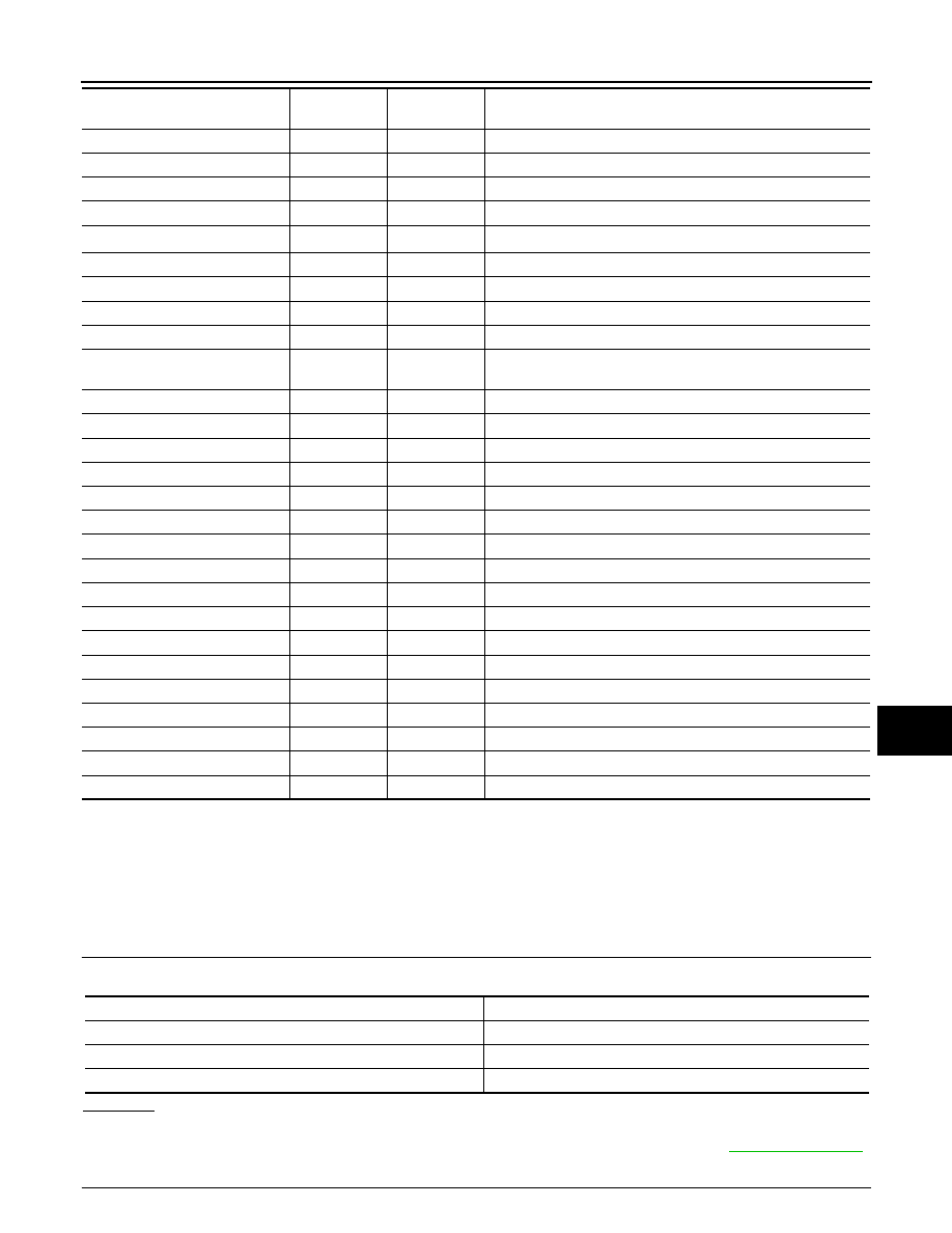
Display item [Code]
Malfunction is detected when...
Reference
page
CAN COMM CIRC [U1000]
When unified meter and A/C amp. is not transmitting or receiving CAN communication
signal for 2 seconds or more.
METER COMM CIRC [B2202]
Malfunction is detected in communication of between combination meter and unified
meter and A/C amp.
VEHICLE SPEED CIRC [B2205]
When an erroneous speed signal is input for 1 second.
NOTE:
Even when there is no malfunction on speed signal system, malfunction may be misin-
terpreted when battery has low voltage (when maintaining 7 - 8 V for about 2 seconds).
Display item [Unit]
MAIN
SIGNALS
SELECTION
FROM MENU
Contents
SPEED METER [km/h] or [mph]
X
X
Displays the value of vehicle speed signal, which is input from
ABS actuator and electric unit (control unit).
SPEED OUTPUT [km/h] or [mph]
X
X
Displays the value of vehicle speed signal, which is transmitted
to each unit with CAN communication.
TACHO METER [rpm]
X
X
Displays the value of engine speed signal, which is input from
ECM.
W TEMP METER [
°
C] or [
°
F]
X
X
Displays the value of engine coolant temperature signal, which is
input from ECM.
FUEL METER [lit.]
X
X
Displays the value, which processes a resistance signal from fuel
gauge.
DISTANCE [km] or [mile]
X
X
Displays the value, which is calculated by vehicle speed signal
from ABS actuator and electric unit (control unit), fuel gauge and
fuel consumption from ECM.
FUEL W/L [On/Off]
X
X
Indicates [On/Off] condition of low-fuel warning lamp.
MIL [On/Off]
X
Indicates [On/Off] condition of malfunction indicator lamp.
AIR PRES W/L [On/Off]
X
Indicates [On/Off] condition of low tire pressure warning lamp.
SEAT BELT W/L [On/Off]
*1
X
Indicates [On/Off] condition of seat belt warning lamp.
BUZZER [On/Off]
X
X
Indicates [On/Off] condition of buzzer.
DOOR W/L [On/Off]
X
Indicates [On/Off] condition of door warning lamp.
HI-BEAM IND [On/Off]
X
Indicates [On/Off] condition of high beam indicator.
TURN IND [On/Off]
X
Indicates [On/Off] condition of turn indicator.
UNIFIED METER AND A/C AMP
DI-29
< SERVICE INFORMATION >
C
D
E
F
G
H
I
J
L
M
A
B
DI
N
O
P
NOTE:
Monitored item that does not match the vehicle is deleted from the display automatically.
*1: It dose not change when fastening or unfastening the passenger seat belt.
*2: Monitor keeps indicating “off” when brake warning lamp is on by the parking brake operation or low brake fluid level.
Power Supply and Ground Circuit Inspection
INFOID:0000000001328459
1.
CHECK FUSE
Check for blown unified meter and A/C amp. fuses.
OK or NG
OK
>> GO TO 2.
NG
>> Be sure to eliminate cause of malfunction before installing new fuse. Refer to
.
2.
CHECK POWER SUPPLY CIRCUIT
OIL W/L [On/Off]
X
Indicates [On/Off] condition of oil pressure warning lamp.
VDC/TCS IND [On/Off]
X
Indicates [On/Off] condition of VDC OFF indicator lamp.
ABS W/L [On/Off]
X
Indicates [On/Off] condition of ABS warning lamp.
SLIP IND [On/Off]
X
Indicates [On/Off] condition of SLIP indicator lamp.
BRAKE W/L [On/Off]
*2
X
Indicates [On/Off] condition of brake warning lamp.
KEY G W/L [On/Off]
X
Indicates [On/Off] condition of key warning lamp (green).
KEY R W/L [On/Off]
X
Indicates [On/Off] condition of key warning lamp (red).
KEY KNOB W/L [On/Off]
X
Indicates [On/Off] condition of key knob warning lamp.
M RANGE SW [On/Off]
X
X
Indicates [On/Off] condition of manual mode range switch.
NM RANGE SW [On/Off]
X
X
Indicates [On/Off] condition of except for manual mode range
switch.
AT SFT UP SW [On/Off]
X
X
Indicates [On/Off] condition of A/T shift-up switch.
AT SFT DWN SW [On/Off]
X
X
Indicates [On/Off] condition of A/T shift-down switch.
BRAKE SW [On/Off]
X
Indicates [On/Off] condition of brake switch (stop lamp switch).
AT-M IND [On/Off]
X
X
Indicates [On/Off] condition of A/T manual mode indicator.
AT-M GEAR [5-1]
X
X
Indicates [5-1] condition of A/T manual mode gear position.
P RANGE IND [On/Off]
X
X
Indicates [On/Off] condition of A/T shift P range indicator.
R RANGE IND [On/Off]
X
X
Indicates [On/Off] condition of A/T shift R range indicator.
N RANGE IND [On/Off]
X
X
Indicates [On/Off] condition of A/T shift N range indicator.
D RANGE IND [On/Off]
X
X
Indicates [On/Off] condition of A/T shift D range indicator.
AT CHECK W/L
X
Indicates [On/Off] condition of AT CHECK warning lamp.
CRUISE IND [On/Off]
X
Indicates [On/Off] condition of CRUISE indicator lamp.
SET IND [On/Off]
X
Indicates [On/Off] condition of SET indicator lamp.
CRUISE W/L [On/Off]
X
Indicates [On/Off] condition of ICC warning lamp.
4WD LOCK SW [On/Off]
X
This item is not used for this model. “off” is always displayed.
4WD LOCK IND [On/Off]
X
This item is not used for this model. “off” is always displayed.
4WD W/L [On/Off]
X
Indicates [On/Off] condition of AWD warning lamp.
RR COMB STATE [OK/NG]
X
Indicates [OK/NG] condition of rear combination lamp circuit.
Display item [Unit]
MAIN
SIGNALS
SELECTION
FROM MENU
Contents
Power source
Fuse No.
Battery power supply
19
ACC power supply
10, 11
Ignition power supply
12
DI-30
< SERVICE INFORMATION >
UNIFIED METER AND A/C AMP
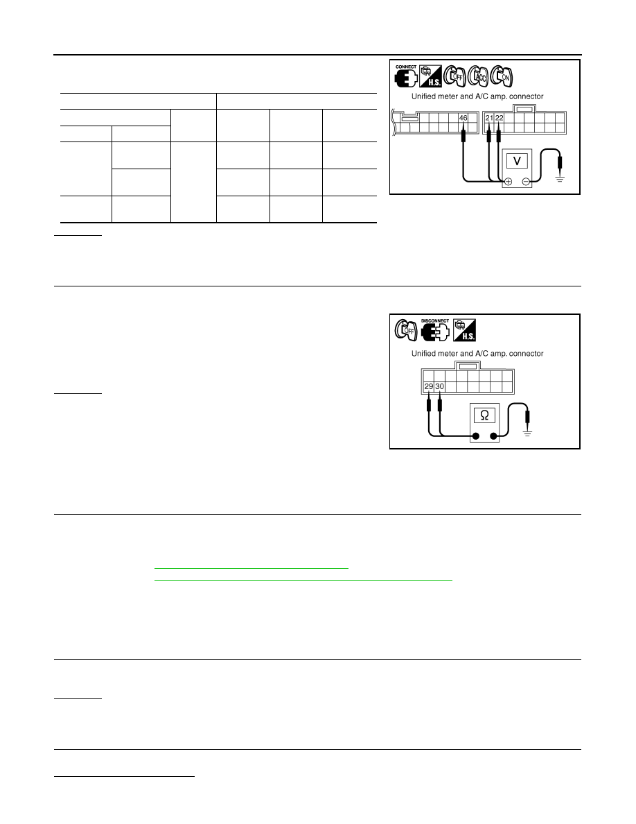
Check voltage between unified meter and A/C amp. harness con-
nector terminals and ground.
OK or NG
OK
>> GO TO 3.
NG
>> Check harness between unified meter and A/C amp. and fuse.
3.
CHECK GROUND CIRCUIT
1.
Turn ignition switch OFF.
2.
Disconnect unified meter and A/C amp. connector.
3.
Check continuity between unified meter and A/C amp. harness
connector M56 terminals 29, 30 and ground.
OK or NG
OK
>> INSPECTION END
NG
>> Repair harness or connector.
DTC [U1000] CAN Communication Circuit
INFOID:0000000001328460
Symptom: Display “CAN COMM CIRC [U1000]” at the result of self-diagnosis for unified meter and A/C amp.
1.
CHECK CAN COMMUNICATION
1.
Turn ignition switch ON and wait for 2 seconds or more.
2.
Check “Self Diagnostic Result” of “METER/M&A”
YES
>> Refer to
LAN-14, "Trouble Diagnosis Flow Chart"
NO
>> Refer to
GI-35, "CONSULT-III/GST Data Link Connector (DLC) Circuit"
DTC [B2202] Meter Communication Circuit
INFOID:0000000001328461
Symptom: Display “METER COMM CIRC [B2202]” at the result of self-diagnosis for unified meter and A/C
amp.
1.
CHECK CONNECTOR
Check combination meter, unified meter and A/C amp. and terminals (combination meter side, unified meter
and A/C amp. side, and harness side) for looseness or bent terminals.
OK or NG
OK
>> GO TO 2.
NG
>> Repair terminal or connector.
2.
CHECK METER/GAUGES VISUALLY
Check the pointer on the meter/gauge fluctuate at the engine start.
Is the fluctuation acceptable?
YES
>> GO TO 3.
Terminals
Ignition switch position
(+)
(–)
OFF
ACC
ON
Connector
Terminal
M56
21
Ground
Battery
voltage
Battery
voltage
Battery
voltage
22
0 V
0 V
Battery
voltage
M57
46
0 V
Battery
voltage
Battery
voltage
PKIB3570E
29 – Ground
: Continuity should exist.
30 – Ground
SKIA5202E
Нет комментариевНе стесняйтесь поделиться с нами вашим ценным мнением.
Текст