Infiniti FX35 / FX45. Manual — part 286
COMBINATION METERS
DI-19
< SERVICE INFORMATION >
C
D
E
F
G
H
I
J
L
M
A
B
DI
N
O
P
Engine Coolant Temperature Signal Inspection
INFOID:0000000001328447
Symptom: Water temperature gauge indication is malfunction.
1.
CHECK COMBINATION METER INPUT SIGNAL
1.
Connect CONSULT-III, and start engine.
2.
Select “METER/M&A” on CONSULT-III.
3.
Using “W TEMP METER” on “Data Monitor”, compare the value of “Data Monitor” with water temperature
gauge pointer of combination meter.
OK or NG
OK
>> GO TO 2.
NG
>> Replace combination meter.
2.
CHECK UNIFIED METER AND A/C AMP. INPUT SIGNAL
Select “Data Monitor” of CONSULT-“COOLAN TEMP/S” of “ENGINE” and “W TEMP METER” of “METER/
M&A”.
OK or NG
OK
>> Perform self-diagnosis of ECM. Refer to
EC-117, "CONSULT-III Function (ENGINE)"
or
EC-695, "CONSULT-III Function (ENGINE)"
(VK45DE).
NG
>> Replace unified meter and A/C amp. Refer to
DI-32, "Removal and Installation of Unified Meter
.
Fuel Level Sensor Signal Inspection
INFOID:0000000001328448
Symptom:
• Fuel gauge indication is malfunctioning.
• Low-fuel warning lamp indication is irregular.
NOTE:
The following symptoms are not malfunctions.
Fuel gauge
• Depending on vehicle posture or driving circumstance, the fuel level in the tank varies, and the pointer may
fluctuate.
• If the vehicle is fueled with the ignition switch ON, the pointer will move slowly.
Low-fuel warning lamp
• Depending on vehicle posture or driving circumstance, the fuel in the tank flows and the warning lamp ON
timing may change.
1.
CHECK COMBINATION METER INPUT SIGNAL
1.
Select “METER A/C AMP” on CONSULT-III.
2.
Using “FUEL METER” on “Data Monitor”, compare the value of “Data Monitor” with fuel gauge pointer of
combination meter.
OK or NG
Water temperature gauge pointer
Reference value of data monitor [
°
C (
°
F)]
Hot
Approx. 130 (266)
Middle
Approx. 70 - 105 (158 - 221)
Cold
Approx. 50 (122)
Fuel gauge pointer
Reference value of data monitor [lit.]
Full
Approx. 86
Three quarters
Approx. 70
Half
Approx. 48
A quarter
Approx. 25
Empty
Approx. 9

DI-20
< SERVICE INFORMATION >
COMBINATION METERS
OK
>> GO TO 2.
NG
>> Replace combination meter.
2.
CHECK FUEL LEVEL SENSOR (SUB) CIRCUIT
1.
Turn ignition switch OFF.
2.
Disconnect unified meter and A/C amp. connector and fuel level sensor unit (sub) connector.
3.
Check continuity between unified meter and A/C amp. harness
connector (A) M56 terminal 28 and fuel level sensor unit (sub)
harness connector (B) B40 terminal 1.
4.
Check continuity between unified meter and A/C amp. harness
connector (A) M56 terminal 28 and ground.
OK or NG
OK
>> GO TO 3.
NG
>> Repair harness or connector.
3.
CHECK FUEL LEVEL SENSOR (MAIN·SUB) CIRCUIT
1.
Disconnect fuel level sensor unit and fuel pump (main) connector.
2.
Check continuity between fuel level sensor unit (sub) harness
connector (A) B40 terminal 2 and fuel level sensor unit and fuel
pump (main) harness connector (B) B39 terminal 2.
3.
Check continuity between fuel level sensor unit (sub) harness
connector (A) B40 terminal 2 and ground.
OK or NG
OK
>> GO TO 4.
NG
>> Repair harness or connector.
4.
CHECK FUEL LEVEL SENSOR (MAIN) CIRCUIT
1.
Check continuity between fuel level sensor unit and fuel pump
(main) harness connector (A) B39 terminal 5 and unified meter
and A/C amp. harness connector (B) M56 terminal 36.
2.
Check continuity between fuel level sensor unit and fuel pump
(main) harness connector (A) B39 terminal 5 and ground.
OK or NG
OK
>> GO TO 5.
NG
>> Repair harness or connector.
5.
CHECK FUEL LEVEL SENSOR
Check components. Refer to
DI-21, "Electrical Component Inspection"
OK or NG
OK
>> Check fuel level sensor unit installation, and check whether the float arm interferes or binds with
any of the internal components in the fuel tank. Repair or replace malfunctioning part, if neces-
sary.
NG
>> Replace fuel level sensor unit.
28 – 1
: Continuity should exist.
28 – Ground
: Continuity should not exist.
SKIB8527E
2 – 2
: Continuity should exist.
2 – Ground
: Continuity should not exist.
SKIB8697E
5 – 36
: Continuity should exist.
5 – Ground
: Continuity should not exist.
SKIB8528E

COMBINATION METERS
DI-21
< SERVICE INFORMATION >
C
D
E
F
G
H
I
J
L
M
A
B
DI
N
O
P
Fuel Gauge Pointer Fluctuates, Indicator Wrong Value or Varies
INFOID:0000000001328449
1.
CHECK FUEL GAUGE FLUCTUATION
Test drive vehicle to see if gauge fluctuates only during driving or at the instant of stopping.
Does the indication value vary only during driving or at the instant of stopping?
YES
>> The pointer fluctuation may be caused by fuel level change in the fuel tank. Condition is normal.
NO
>> Ask the customer about the situation when the symptom occurs in detail, and perform the trouble
diagnosis.
Fuel Gauge Does Not Move to FULL Position
INFOID:0000000001328450
1.
QUESTION 1
Does it take a long time for the pointer to move to FULL position?
YES
>> GO TO 2.
NO
>> GO TO 3.
2.
QUESTION 2
Was the vehicle fueled with the ignition switch ON?
YES
>> Be sure to fuel the vehicle with the ignition switch OFF. Otherwise, it will take a long time to move
to FULL position because of the characteristic of the fuel gauge.
NO
>> GO TO 3.
3.
QUESTION 3
Is the vehicle parked on an incline?
YES
>> Check the fuel level indication with vehicle on a level surface.
NO
>> GO TO 4.
4.
QUESTION 4
During driving, does the fuel gauge pointer move gradually toward EMPTY position?
YES
>> Check the fuel level sensor unit. Refer to
DI-21, "Electrical Component Inspection"
NO
>> The float arm may interfere or bind with any of the components in the fuel tank.
Odo/Trip Meter and Illumination Control Switch Inspection
INFOID:0000000001328451
Symptom: Illumination control does not operate.
1.
CHECK ODO/TRIP METER AND ILLUMINATION CONTROL SWITCH
1.
Remove odo/trip meter and illumination control switch. Refer to
DI-24, "Removal and Installation of Odo/
Trip Meter and Illumination Control Switch"
.
2.
Check continuity odo/trip meter and illumination control switch. Refer to
.
OK or NG
OK
>> Replace combination meter.
NG
>> Replace odo/trip meter and illumination control switch.
Electrical Component Inspection
INFOID:0000000001328452
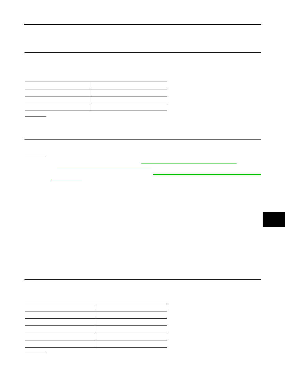
ODO/TRIP METER AND ILLUMINATION CONTROL SWITCH
DI-22
< SERVICE INFORMATION >
COMBINATION METERS
Check continuity between terminals 25, 26, 35 or 36 and 27.
FUEL LEVEL SENSOR UNIT
For removal, refer to
.
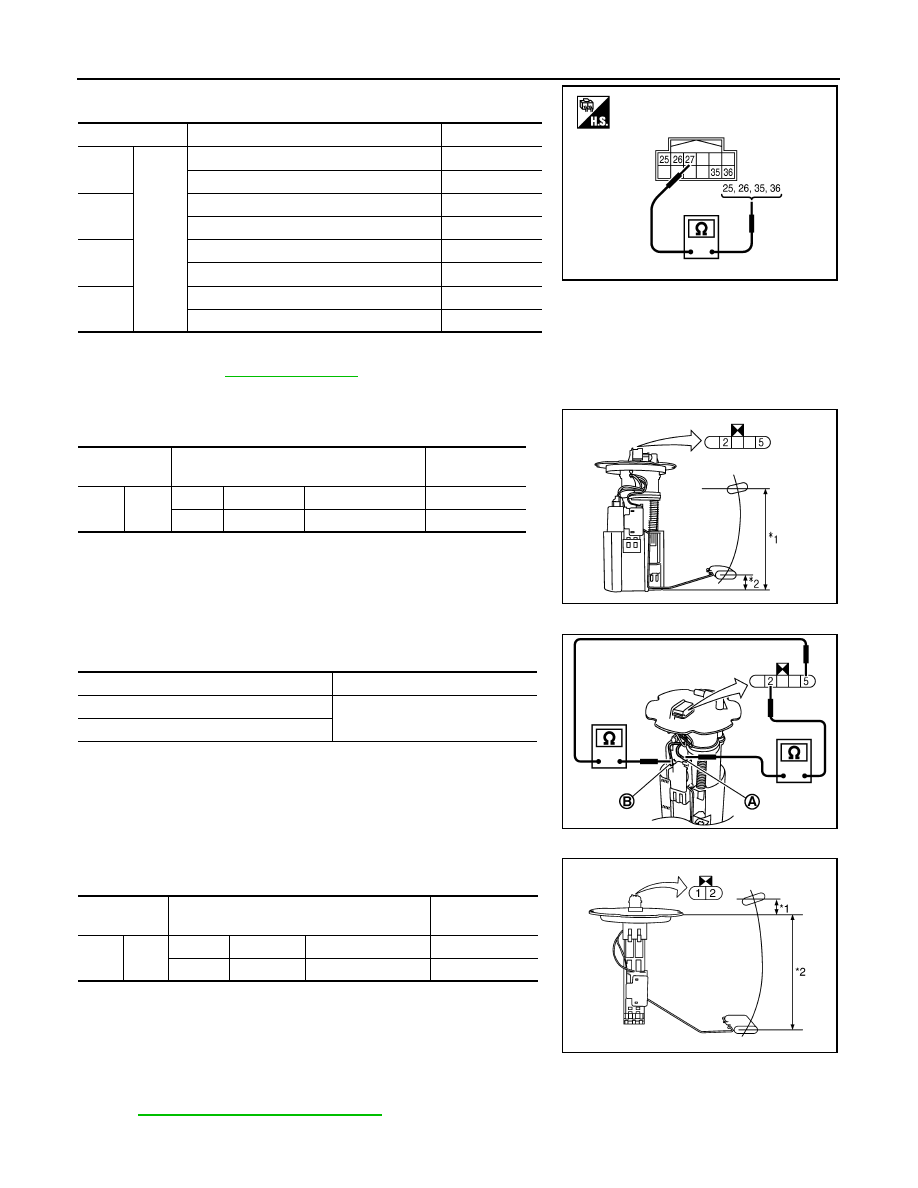
Fuel Level Sensor Unit and Fuel Pump (Main)
Check the resistance between terminals 2 and 5.
*1 and *2: When float rod is in contact with stopper.
• If the results of check are NG, check the fuel level sensor unit and
fuel pump (main) harness. Refer to "Fuel Level Sensor Unit and
Pump (Main) Harness".
Fuel Level Sensor Unit and Pump (Main) Harness
Check continuity at following terminals.
• If the results of check are NG, replace fuel pump assembly. If the
results of check are OK, replace fuel level sensor unit.
Fuel Level Sensor Unit (Sub)
Check resistance between terminals 1 and 2.
*1 and *2: When float rod is in contact with stopper.
Removal and Installation of Combination Meter
INFOID:0000000001328453
IP-10, "Component Parts Location"
Terminal
Condition
Continuity
25
27
Illumination control switch (–) is pressed.
Yes
Illumination control switch (–) is released.
No
26
Illumination control switch (+) is pressed.
Yes
Illumination control switch (+) is released.
No
35
Trip transfer switch is pressed.
Yes
Trip transfer switch is released.
No
36
Trip reset switch is pressed.
Yes
Trip reset switch is released.
No
SKIB8529E
Terminal
Float position
[mm (in)]
Resistance val-
ue [
Ω
]
2
5
*1
Full
236 (9.29)
Approx. 3
*2
Empty
29 (1.14)
Approx. 80
SKIB3550J
Terminal
Continuity
2 - Signal terminal (A)
Yes
5 - Ground terminal (B)
SKIB3551J
Terminal
Float position
[mm (in)]
Resistance val-
ue [
Ω
]
1
2
*1
Full
6 (0.24)
Approx. 3
*2
Empty
203 (7.99)
Approx. 48
SKIB8530E
Нет комментариевНе стесняйтесь поделиться с нами вашим ценным мнением.
Текст