Infiniti FX35 / FX45. Manual — part 805
STOP LAMP
LT-115
< SERVICE INFORMATION >
C
D
E
F
G
H
I
J
L
M
A
B
LT
N
O
P
1.
Remove cap from back door finisher and remove nuts. Refer to
EI-47, "Component Parts Location"
2.
Disconnect high-mounted stop lamp connector.
3.
Remove washer tube from high-mounted stop lamp, and
remove high-mounted stop lamp from the rear air spoiler.
4.
Remove seal packing from the rear air spoiler.
5.
Installation is the reverse order of removal.
CAUTION:
Seal packing cannot be reused.
Stop Lamp
INFOID:0000000001328377
BULB REPLACEMENT
.
REMOVAL AND INSTALLATION
LT-137, "Removal and Installation"
Rear Combination Lamp Control Unit
INFOID:0000000001328378
REMOVAL AND INSTALLATION
LT-95, "Removal and Installation of Rear Combination Lamp Control Unit"
.
High-mounted stop lamp
: LED
SKIA5562E
LT-116
< SERVICE INFORMATION >
BACK-UP LAMP
BACK-UP LAMP
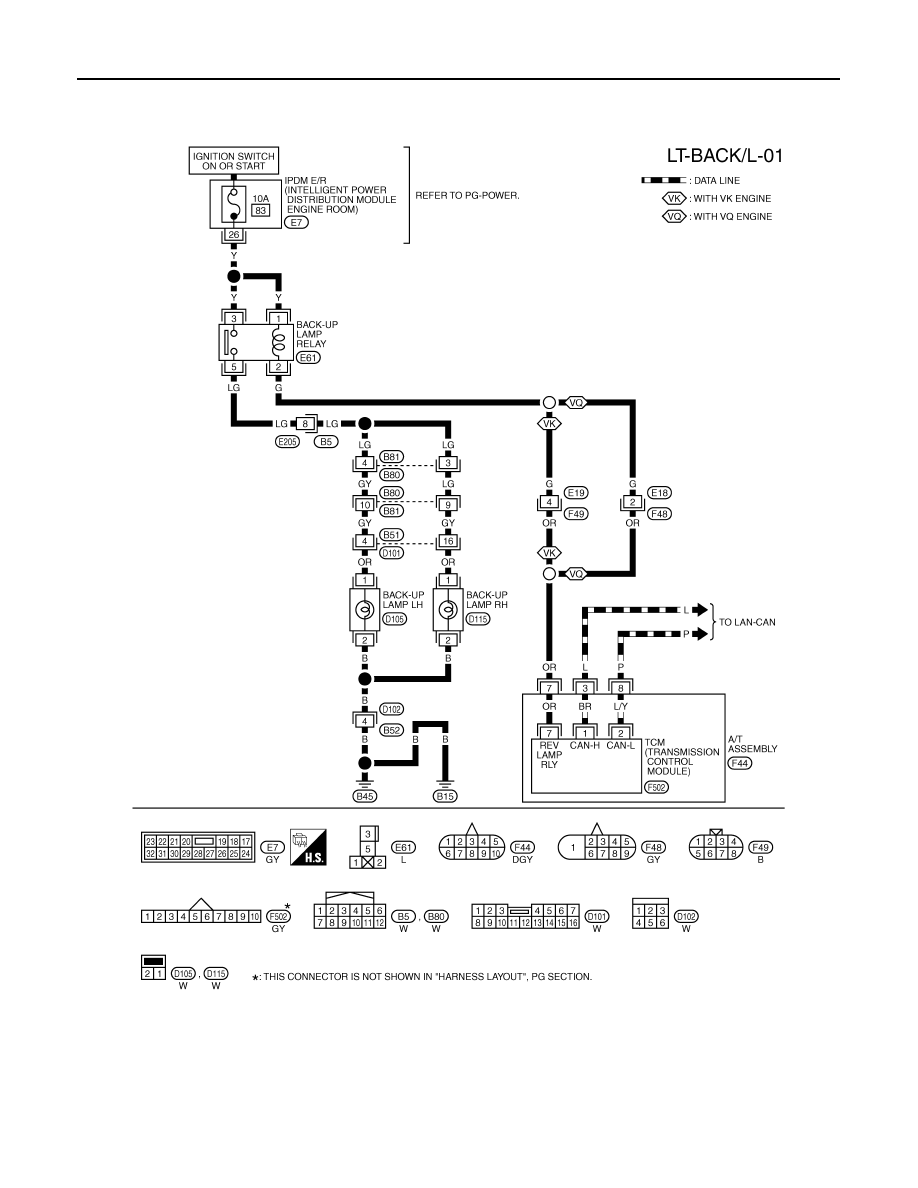
Wiring Diagram - BACK/L -
INFOID:0000000001328379
TKWM4313E
BACK-UP LAMP
LT-117
< SERVICE INFORMATION >
C
D
E
F
G
H
I
J
L
M
A
B
LT
N
O
P
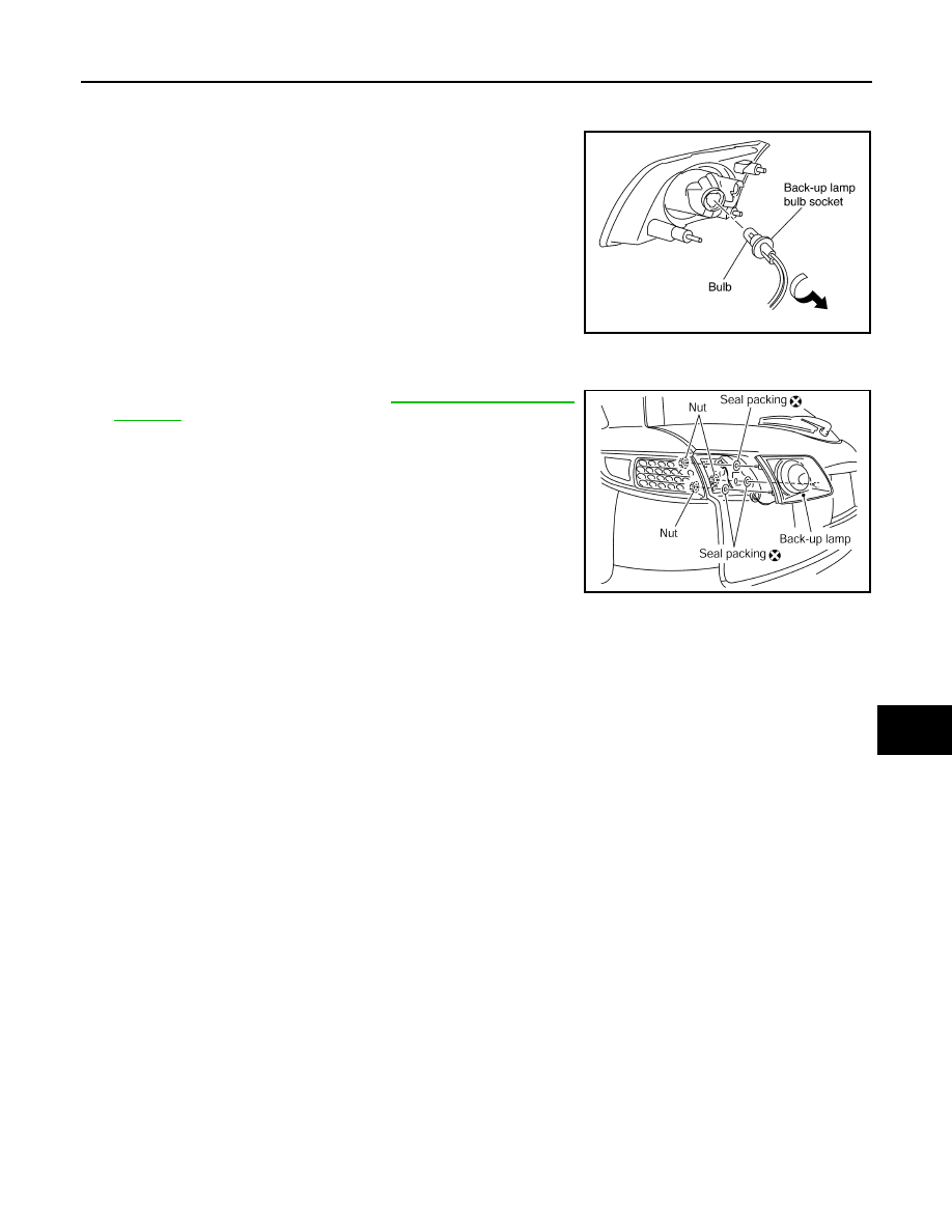
Bulb Replacement
INFOID:0000000001328380
1.
Remove rear combination lamp (back door side).
2.
Turn bulb socket counterclockwise and unlock it.
3.
Remove bulb.
Removal and Installation
INFOID:0000000001328381
1.
Remove back door finisher. Refer to
2.
Disconnect rear combination lamp connector.
3.
Remove rear combination lamp mounting nuts.
4.
Remove rear combination lamp from back door.
5.
Remove seal packing from back door.
Back-up lamp
: 12 V - 18 W
PKIB3634E
PKIB3635E
LT-118
< SERVICE INFORMATION >
PARKING, LICENSE PLATE AND TAIL LAMPS
PARKING, LICENSE PLATE AND TAIL LAMPS
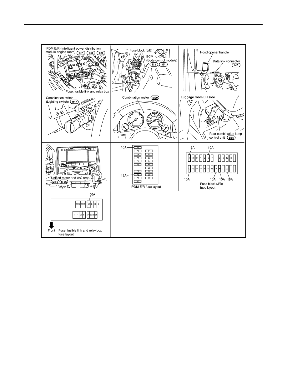
Component Parts and Harness Connector Location
INFOID:0000000001328382
System Description
INFOID:0000000001328383
Control of the parking, license plate, side marker and tail lamp operation is dependent upon the position of the
lighting switch (combination switch). When the lighting switch is placed in the 1ST position, the BCM (body
control module) receives input signal requesting the parking, license plate, side marker and tail lamps to illumi-
nate. This input signal is communicated to the IPDM E/R (intelligent power distribution module engine room)
through the CAN communication lines. CPU (central processing unit) located in the IPDM E/R controls the tail
lamp relay coil. This relay, when energized, directs power to the parking, license plate, side marker and tail
lamps, which then illuminate.
The current that flows by Rear combination lamp control unit is controlled, and a tail lamp (LED) is made to
turn ON.
OUT LINE
Power is supplied at all times
• to ignition relay, located in IPDM E/R, from battery direct,
• through 10A fuse (No. 71, located in IPDM E/R)
• to tail lamp relay, located in IPDM E/R and
• to CPU located in IPDM E/R,
• through 15A fuse (No. 78, located in IPDM E/R)
• to CPU located in IPDM E/R.
• through 50A fusible link (letter M, located in fuse, fusible link and relay box)
PKIC9694E
Нет комментариевНе стесняйтесь поделиться с нами вашим ценным мнением.
Текст