Infiniti FX35 / FX45. Manual — part 56
AT-152
< SERVICE INFORMATION >
DTC P1772 LOW COAST BRAKE SOLENOID VALVE
OK or NG
OK
>> GO TO 4.
NG
>> GO TO 2.
2.
CHECK TCM POWER SUPPLY AND GROUND CIRCUIT
Check TCM power supply and ground circuit. Refer to
OK or NG
OK
>> GO TO 3.
NG
>> Repair or replace damaged parts.
3.
DETECT MALFUNCTIONING ITEM
Check A/T assembly harness connector pin terminals for damage or loose connection with harness connector.
OK or NG
OK
>> Replace the control valve with TCM. Refer to
AT-215, "Control Valve with TCM and A/T Fluid Tem-
.
NG
>> Repair or replace damaged parts.
4.
CHECK DTC
Perform
AT-151, "DTC Confirmation Procedure"
.
OK or NG
OK
>> INSPECTION END
NG
>> GO TO 2.

DTC P1774 LOW COAST BRAKE SOLENOID VALVE FUNCTION
AT-153
< SERVICE INFORMATION >
D
E
F
G
H
I
J
K
L
M
A
B
AT
N
O
P
DTC P1774 LOW COAST BRAKE SOLENOID VALVE FUNCTION
Description
INFOID:0000000001327313
• Low coast brake solenoid valve is turned ON or OFF by the TCM in response to signals sent from the PNP
switch, vehicle speed sensor and accelerator pedal position sensor (throttle position sensor). Gears will then
be shifted to the optimum position.
• This is not only caused by electrical malfunction (circuits open or shorted) but also by mechanical malfunc-
tion such as control valve sticking, improper solenoid valve operation.
CONSULT-III Reference Value in Data Monitor Mode
INFOID:0000000001327314
On Board Diagnosis Logic
INFOID:0000000001327315
Diagnostic trouble code “P1774 LC/B SOLENOID FNCT” with CONSULT-III or 7th judgement flicker without
CONSULT-III is detected under the following conditions.
• When TCM detects that actual gear ratio is irregular, and relation between gear position and condition of
ATF pressure switch 2 is irregular during depressing accelerator pedal. (Other than during shift change)
• When TCM detects that relation between gear position and condition of ATF pressure switch 2 is irregular
during releasing accelerator pedal. (Other than during shift change)
Possible Cause
INFOID:0000000001327316
• Harness or connectors
(Solenoid and switch circuits are open or shorted.)
• Low coast brake solenoid valve
• ATF pressure switch 2
DTC Confirmation Procedure
INFOID:0000000001327317
CAUTION:
Always drive vehicle at a safe speed.
NOTE:
If “DTC Confirmation Procedure” has been previously performed, always turn ignition switch OFF and
wait at least 10 seconds before performing the next test.
After the repair, perform the following procedure to confirm the malfunction is eliminated.
WITH CONSULT-III
1.
Start engine.
2.
Accelerate vehicle to maintain the following conditions.
MANU MODE SW: ON
GEAR: “1” or “2” (LC/B ON/OFF)
3.
Perform step “2” again.
4.
Turn ignition switch OFF, then perform step “1” to “3” again.
5.
Check “SELF-DIAG RESULTS” mode for “TRANSMISSION” with CONSULT-III. If DTC (P1774) is
detected, go to
.
If DTC (P1772) is detected, go to
WITH GST
Follow the procedure “WITH CONSULT-III”.
Diagnosis Procedure
INFOID:0000000001327318
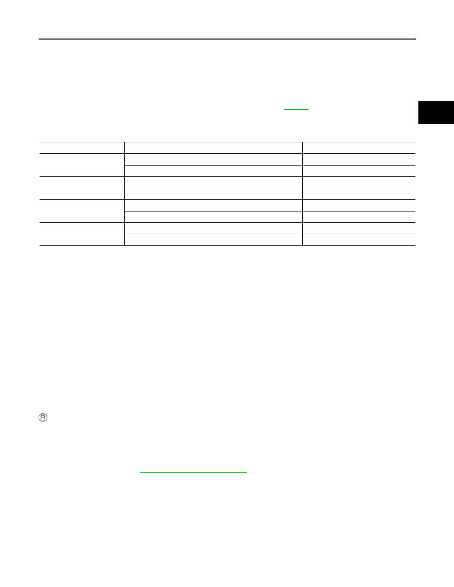
1.
CHECK INPUT SIGNALS
Item name
Condition
Display value
ON OFF SOL
Low coast brake engaged. Refer to
.
ON
Low coast brake disengaged. Refer to
.
OFF
ATF PRES SW 2
Low coast brake engaged. Refer to
.
ON
Low coast brake disengaged. Refer to
.
OFF

AT-154
< SERVICE INFORMATION >
DTC P1774 LOW COAST BRAKE SOLENOID VALVE FUNCTION
With CONSULT-III
1.
Start engine.
2.
Select “SELECTION FROM MENU” in “DATA MONITOR” mode for “TRANSMISSION” with CONSULT-III.
3.
Drive vehicle in the manual mode (1st or 2nd gear), and confirm the ON/OFF actuation of the “ATF PRES
SW 2” and “ON OFF SOL”.
OK or NG
OK
>> GO TO 4.
NG
>> GO TO 2.
2.
CHECK TCM POWER SUPPLY AND GROUND CIRCUIT
Check TCM power supply and ground circuit. Refer to
OK or NG
OK
>> GO TO 3.
NG
>> Repair or replace damaged parts.
3.
DETECT MALFUNCTIONING ITEM
Check A/T assembly harness connector pin terminals for damage or loose connection with harness connector.
OK or NG
OK
>> Replace the control valve with TCM. Refer to
AT-215, "Control Valve with TCM and A/T Fluid Tem-
.
NG
>> Repair or replace damaged parts.
4.
CHECK DTC
Perform
AT-153, "DTC Confirmation Procedure"
.
OK or NG
OK
>> INSPECTION END
NG
>> GO TO 2.
Item name
Condition
Display value
ON OFF SOL
Low coast brake engaged. Refer to
ON
Low coast brake disengaged. Refer to
.
OFF
ATF PRES SW 2
Low coast brake engaged. Refer to
ON
Low coast brake disengaged. Refer to
.
OFF
DTC P1815 MANUAL MODE SWITCH
AT-155
< SERVICE INFORMATION >
D
E
F
G
H
I
J
K
L
M
A
B
AT
N
O
P
DTC P1815 MANUAL MODE SWITCH
Description
INFOID:0000000001327319
Manual mode switch is installed in A/T device. It sends manual mode switch, shift up and shift down switch
signals to TCM.
TCM sends the switch signals to unified meter and A/C amp. by CAN communication line. Then manual mode
switch position is indicated on the A/T indicator. For inspection, refer to
.
CONSULT-III Reference Value in Data Monitor Mode
INFOID:0000000001327320
On Board Diagnosis Logic
INFOID:0000000001327321
Diagnostic trouble code “P1815 MANU MODE SW/CIR” with CONSULT-IIII is detected when TCM monitors
Manual mode, Non manual mode, Up or Down switch signal, and detects as irregular when impossible input
pattern occurs 1 second or more.
Possible Cause
INFOID:0000000001327322
• Harness or connectors
(These switches circuit is open or shorted.)
• Manual mode select switch (Into control device)
• Manual mode position select switch (Into control device)
DTC Confirmation Procedure
INFOID:0000000001327323
NOTE:
If “DTC Confirmation Procedure” has been previously performed, always turn ignition switch OFF and
wait at least 10 seconds before performing the next test.
After the repair, perform the following procedure to confirm the malfunction is eliminated.
WITH CONSULT-III
1.
Turn ignition switch ON.
2.
Select “ECU INPUT SIGNALS” in “DATA MONITOR” mode for “TRANSMISSION” with CONSULT-III.
3.
Start engine.
4.
Drive vehicle and maintain the following conditions for at least 2 consecutive seconds.
MANU MODE SW: ON
5.
If DTC is detected, go to
Item name
Condition
Display Value
MANU MODE SW
Manual shift gate position (neutral)
ON
Other than the above
OFF
NON M-MODE SW
Manual shift gate position
OFF
Other than the above
ON
UP SW LEVER
selector lever: + side
ON
Other than the above
OFF
DOWN SW LEVER
selector lever: - side
ON
Other than the above
OFF
Нет комментариевНе стесняйтесь поделиться с нами вашим ценным мнением.
Текст