Infiniti FX35 / FX45. Manual — part 638
TIMING CHAIN
EM-69
< SERVICE INFORMATION >
[VQ35DE]
C
D
E
F
G
H
I
J
K
L
M
A
EM
N
P
O
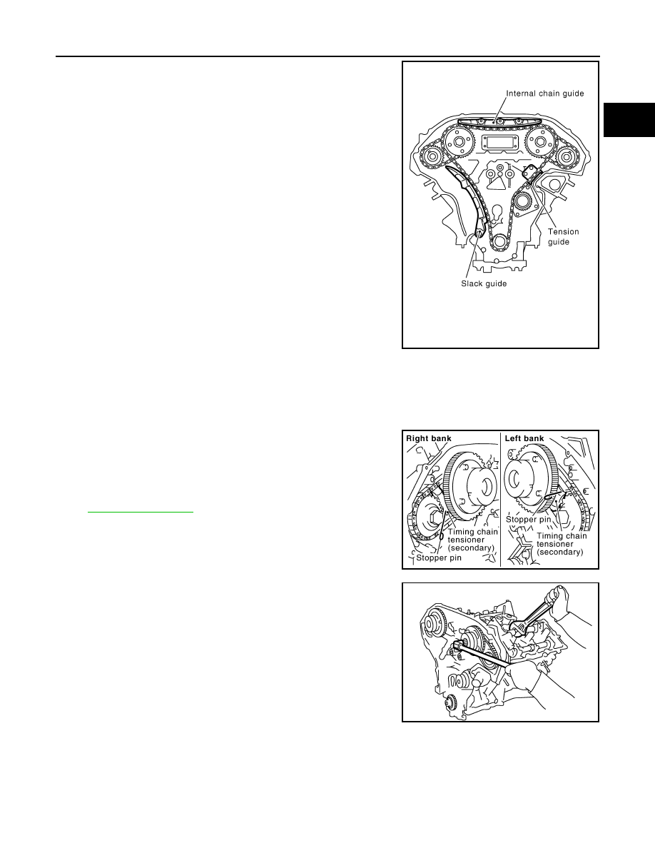
29. Remove internal chain guide, tension guide and slack guide.
NOTE:
Tension guide can be removed after removing timing chain (pri-
mary).
30. Remove timing chain (primary) and crankshaft sprocket.
CAUTION:
After removing timing chain (primary), do not turn crankshaft and camshaft separately, or valves
will strike the piston heads.
31. Remove timing chain (secondary) and camshaft sprockets as follows:
a.
Attach suitable stopper pin to the right and left timing chain ten-
sioners (secondary).
NOTE:
• Use approximately 0.5 mm (0.020 in) dia. hard metal pin as a
stopper pin.
• For removal of timing chain tensioner (secondary), refer to
. [Removing camshaft bracket (No. 1) is
required.]
b.
Remove camshaft sprocket (INT and EXH) mounting bolts.
• Secure the hexagonal portion of camshaft using a wrench to
loosen mounting bolts.
CAUTION:
Do not loosen the mounting bolts with securing anything
other than the camshaft hexagonal portion or with ten-
sioning the timing chain.
c.
Remove timing chain (secondary) together with camshaft sprockets.
• Turn camshaft slightly to secure slackness of timing chain on timing chain tensioner (secondary) side.
PBIC2266E
PBIC2047E
KBIA1698J
EM-70
< SERVICE INFORMATION >
[VQ35DE]
TIMING CHAIN
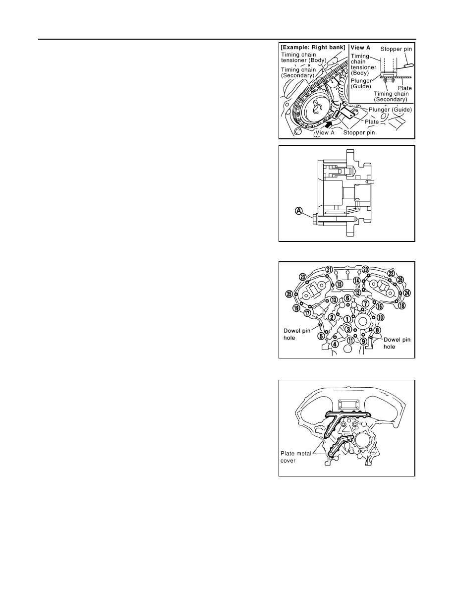
• Insert 0.5 mm (0.020 in)-thick metal or resin plate between tim-
ing chain and timing chain tensioner plunger (guide). Remove
timing chain (secondary) together with camshaft sprockets
with timing chain loose from guide groove.
CAUTION:
Be careful of plunger coming-off when removing timing
chain (secondary). This is because plunger of timing
chain tensioner (secondary) moves during operation,
leading to coming-off of fixed stopper pin.
NOTE:
Camshaft sprocket (INT) is two-for-one structure of primary
and secondary sprockets.
• When handling camshaft sprocket (INT), be careful of the fol-
lowing caution:
CAUTION:
• Handle carefully to avoid any shock to camshaft
sprocket.
• Do not disassemble. (Do not loosen bolts “A” as shown
in the figure).
32. Remove rear timing chain case as follows:
a.
Loosen and remove mounting bolts in reverse order as shown in
the figure.
b.
Cut liquid gasket using the seal cutter [SST: KV10111100
(J37228)] and remove rear timing chain case.
CAUTION:
• Do not remove plate metal cover of oil passage.
• After removal, handle rear timing chain case carefully so
it does not tilt, cant, or warp under a load.
PBIC1978E
PBIC2980E
SEM735G
KBIA1307E
TIMING CHAIN
EM-71
< SERVICE INFORMATION >
[VQ35DE]
C
D
E
F
G
H
I
J
K
L
M
A
EM
N
P
O
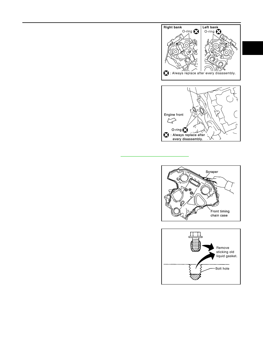
33. Remove O-rings from cylinder head.
34. Remove O-rings from cylinder block.
35. Remove timing chain tensioners (secondary) from cylinder head as follows, if necessary.
a.
Remove camshaft brackets (No. 1). Refer to
EM-84, "Removal and Installation"
b.
Remove timing chain tensioners (secondary) with a stopper pin attached.
36. Use a scraper to remove all traces of liquid gasket from front
and rear timing chain cases, and opposite mating surfaces.
• Remove old liquid gasket from the bolt hole and thread.
SBIA0496E
PBIC0788E
SEM737G
PBIC2084E
EM-72
< SERVICE INFORMATION >
[VQ35DE]
TIMING CHAIN
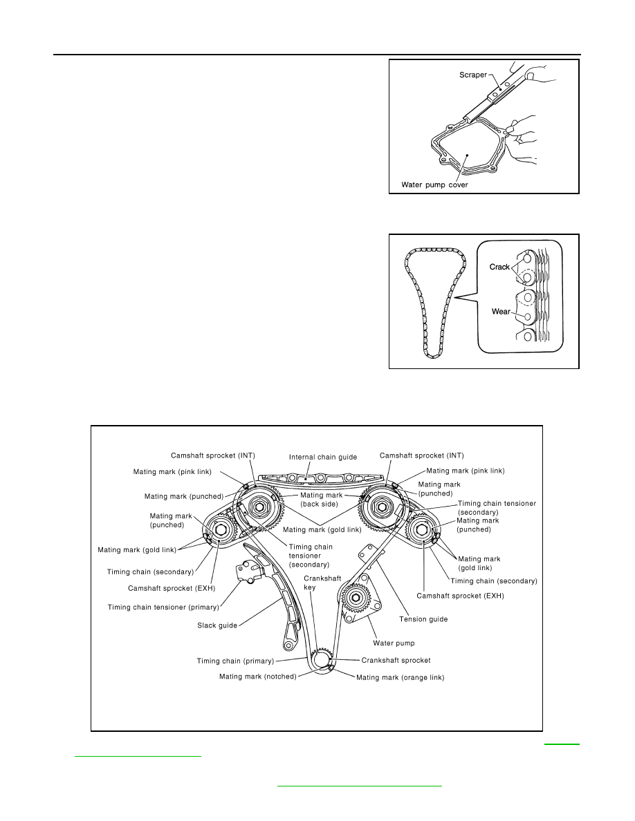
37. Use a scraper to remove all traces of liquid gasket from water
pump cover, chain tensioner cover and intake valve timing con-
trol covers.
INSPECTION AFTER REMOVAL
Timing Chain
Check for cracks and any excessive wear at link plates and roller
links of timing chain. Replace timing chain as necessary.
INSTALLATION
NOTE:
The below figure shows the relationship between the mating mark on each timing chain and that on the corre-
sponding sprocket, with the components installed.
1.
Install timing chain tensioners (secondary) to cylinder head as follows if removed. Refer to
a.
Install timing chain tensioners (secondary) with a stopper pin attached and new O-rings.
b.
Install camshaft brackets (No. 1). Refer to
EM-84, "Removal and Installation"
.
SEM926E
PBIC0282E
PBIC4662E
Нет комментариевНе стесняйтесь поделиться с нами вашим ценным мнением.
Текст