Infiniti FX35 / FX45. Manual — part 637

TIMING CHAIN
EM-65
< SERVICE INFORMATION >
[VQ35DE]
C
D
E
F
G
H
I
J
K
L
M
A
EM
N
P
O
Removal and Installation
INFOID:0000000001325730
NOTE:
• This section describes procedures for removing/installing front timing chain case and timing chain related
parts, and rear timing chain case, when oil pan (upper) needs to be removed/installed for engine overhaul,
etc.
• To remove/install front timing chain case, timing chain, and its related parts without removing oil pan (upper),
refer to
EM-54, "Removal and Installation"
REMOVAL
1.
Remove front tire.
2.
Disconnect negative battery terminal.
3.
Remove engine cover with power tool. Refer to
4.
Remove air cleaner case assembly. Refer to
.
5.
Remove front and rear engine undercover with power tool.
6.
Release the fuel pressure. Refer to
7.
Drain engine coolant from radiator. Refer to
CO-10, "Changing Engine Coolant"
.
CAUTION:
• Perform this step when the engine is cold.
• Do not spill engine coolant on drive belts.
8.
Drain engine oil. Refer to
CAUTION:
• Perform this step when the engine is cold.
• Do not spill engine oil on drive belts.
9.
Remove engine harnesses.
10. Remove intake manifold collectors (upper and lower). Refer to
.
11. Remove radiator cooling fan assembly. Refer to
.
12. Remove drive belts. Refer to
EM-15, "Removal and Installation"
13. Remove A/C compressor from bracket with piping connected, and temporarily secure it aside. Refer to
14. Remove power steering oil pump from bracket with piping connected, and temporarily secure it aside.
PS-27, "On-Vehicle Inspection and Service"
15. Remove power steering oil pump bracket. Refer to
PS-27, "On-Vehicle Inspection and Service"
16. Remove alternator. Refer to
17. Remove water bypass hose, water hose clamp and idler pulley bracket from front timing chain case.
18. Remove intake valve timing control covers.
10. Camshaft sprocket (INT)
11. Slack guide
12.
Crankshaft sprocket
13. Timing chain tensioner (primary)
14. Intake valve timing control cover
15.
Collared O-ring
16. O-ring
17. Chain tensioner cover
18.
Intake valve timing control cover
19. Water hose clamp
20. Spacer
21.
Idler pulley
22. Crankshaft pulley
23. Front oil seal
24.
Idler pulley
25. A/C compressor bracket
26. Water pump cover
27.
Bracket
28. Front timing chain case
29. Bracket
30.
Rear timing chain case
31. O-ring
32. Tension guide
33.
Water drain plug (front side)
EM-66
< SERVICE INFORMATION >
[VQ35DE]
TIMING CHAIN
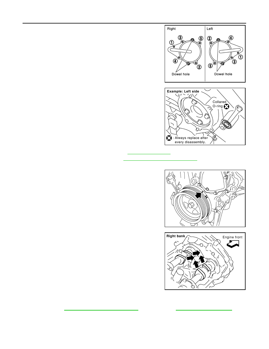
• Loosen mounting bolts in reverse order as shown in the figure.
• Use the seal cutter [SST: KV10111100 (J37228)] to cut liquid
gasket for removal.
CAUTION:
Shaft is internally jointed with camshaft sprocket (INT) cen-
ter hole. When removing, keep it horizontal until it is com-
pletely disconnected.
19. Remove collared O-ring from front timing chain case (left and
right side).
20. Remove rocker covers (right and left). Refer to
.
21. Remove oil pans (lower and upper). Refer to
EM-30, "Component (2WD Models)"
.
22. Obtain No. 1 cylinder at TDC of its compression stroke as follows:
a.
Rotate crankshaft pulley clockwise to align timing mark (grooved
line without color) with timing indicator.
b.
Make sure that intake and exhaust cam noses on No. 1 cylinder
(engine front side of right bank) are located as shown in the fig-
ure.
• If not, turn crankshaft one revolution (360 degrees) and align
as shown in the figure.
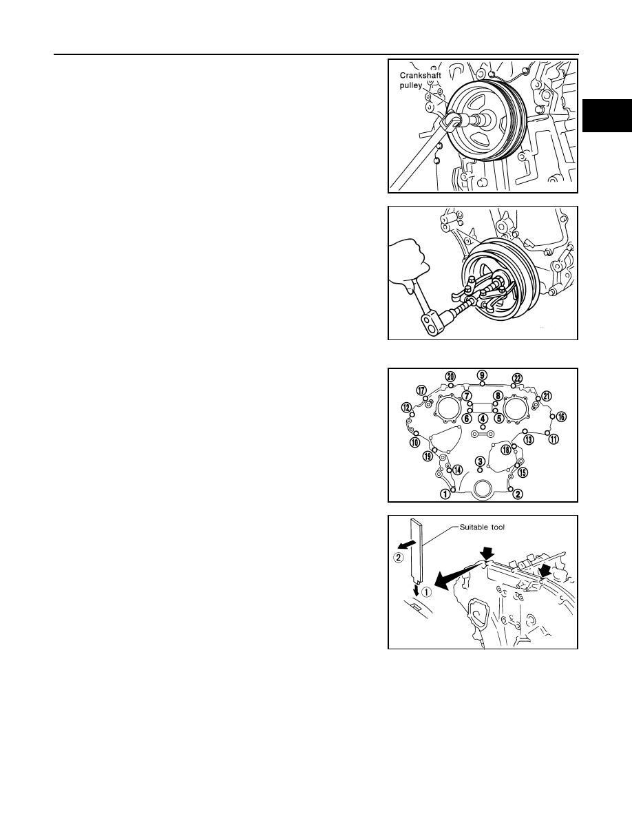
23. Remove crankshaft pulley as follows:
a.
Remove rear cover plate (2WD models) or starter motor (AWD models) and set the ring gear stopper
(SST). Refer to
EM-30, "Component (2WD Models)"
(AWD
models).
SEM728G
PBIC2631E
KBIA1717J
SEM418G
TIMING CHAIN
EM-67
< SERVICE INFORMATION >
[VQ35DE]
C
D
E
F
G
H
I
J
K
L
M
A
EM
N
P
O
b.
Loosen crankshaft pulley bolt and rotate bolt seating surface at
10 mm (0.39 in) from its original position.
CAUTION:
Do not remove crankshaft pulley bolt as it will be used as a
supporting point for suitable puller.
c.
Place suitable puller tab on holes of crankshaft pulley, and pull
crankshaft pulley through.
CAUTION:
Do not put suitable puller tab on crankshaft pulley periph-
ery, as this will damage internal damper.
24. Remove front timing chain case as follows:
a.
Loosen mounting bolts in reverse order as shown in the figure.
b.
Insert a suitable tool into the notch at the top of front timing chain
case as shown (1).
c.
Pry off case by moving the tool as shown (2).
• Use the seal cutter [SST: KV10111100 (J37228)] to cut liquid
gasket for removal.
CAUTION:
• Do not use a screwdriver or something similar.
• After removal, handle front timing chain case carefully so
it does not tilt, cant, or warp under a load.
PBIC1103E
EMQ0477D
KBIA1303E
SEM156F
EM-68
< SERVICE INFORMATION >
[VQ35DE]
TIMING CHAIN
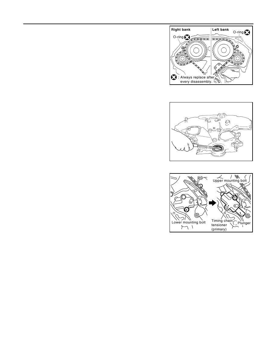
25. Remove O-rings from rear timing chain case.
26. Remove water pump cover and chain tensioner cover from front timing chain case, if necessary.
• Use the seal cutter [SST: KV10111100 (J37228)] to cut liquid gasket for removal.
27. Remove front oil seal from front timing chain case using a suit-
able tool.
• Use a screwdriver for removal.
CAUTION:
Be careful not to damage front timing chain case.
28. Remove timing chain tensioner (primary) as follows:
a.
Remove lower mounting bolt.
b.
Loosen upper mounting bolt slowly, and then turn timing chain
tensioner (primary) on the mounting bolt so that plunger is fully
expanded.
NOTE:
Even if plunger is fully expanded, it is not dropped from the body
of timing chain tensioner (primary).
c.
Remove upper mounting bolt, and then remove timing chain ten-
sioner (primary).
PBIC2548E
EMQ0032D
PBIC3562E
Нет комментариевНе стесняйтесь поделиться с нами вашим ценным мнением.
Текст