Infiniti FX35 / FX45. Manual — part 950

AWD SYSTEM
TF-11
< SERVICE INFORMATION >
C
E
F
G
H
I
J
K
L
M
A
B
TF
N
O
P
AWD SYSTEM
Power Transfer Diagram
INFOID:0000000001327431
System Description
INFOID:0000000001327432
DESCRIPTION
• Electronic control allows optimal distribution of torque to front/rear wheels to match road conditions.
• Makes possible stable driving, with no wheel spin, on snowy roads or other slippery surfaces.
• On roads which do not require AWD, it contributes to improved fuel economy by driving in conditions close to
rear-wheel drive.
• Sensor inputs determine the vehicle's turning condition, and in response tight cornering/braking are con-
trolled by distributing optimum torque to front wheels.
NOTE:
• When driving, if there is a large difference between front and rear wheel speed which continues for a long
time, fluid temperature of drive system parts becomes too high and AWD warning lamp flashes rapidly.
(When AWD warning lamp flashes, vehicle changes to rear-wheel drive conditions.) Also, optional distribu-
tion of torque sometimes becomes rigid before lamp flashes rapidly, but it is not malfunction.
• If AWD warning lamp is flashing rapidly, stop vehicle and allow it to idle for some time. Flashing will stop and
AWD system will be restored.
• When driving, AWD warning lamp may flash slowly if there is a significant difference in diameter of the tires.
At this time, vehicle performance is not fully available and cautious driving is required. (Continues until
engine is turned OFF.)
• If the warning lamp flashes slowly during driving but remains OFF after engine is restarted, the system is
normal. If it again flashes slowly after driving for some time, vehicle must be inspected.
• When the difference of revolution speed between the front and rear wheel mode the shift occasionally
changes to direct 4-wheel driving conditions automatically. This is not malfunction.
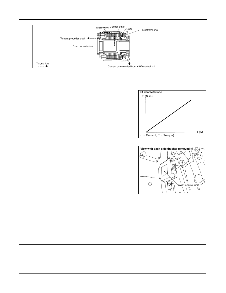
ELECTRIC CONTROLLED COUPLING
Operation Principle
SDIA1611E
TF-12
< SERVICE INFORMATION >
AWD SYSTEM
1.
AWD control unit supplies command current to electric controlled coupling (AWD solenoid).
2.
Control clutch is engaged by electromagnet and torque is detected in control clutch.
3.
The cam operates in response to control clutch torque and applies pressure to main clutch.
4.
Main clutch transmits torque to front wheels according to pressing power.
• Transmission torque to front wheels is determined according
to command current.
AWD CONTROL UNIT
• Controls distribution of drive power between rear-wheel drive
(0:100) and AWD (50:50) conditions according to signals from sen-
sors.
• Self-diagnosis can be done with CONSULT-III.
AWD WARNING LAMP
Turns ON when there is a malfunction in AWD system. It indicates that fail-safe mode is engaged and vehicle
change to rear-wheel drive or shifting driving force-AWD (Front-wheels still have some driving torque).
Also turns ON when ignition switch is turned ON, for purpose of lamp check. Turns OFF approximately for 1
seconds after the engine starts if system is normal.
AWD Warning Lamp Indication
SDIA2270E
SDIA1844E
SDIA2273E
Condition
AWD warning lamp
Lamp check
Turns ON when ignition switch is turned ON. Turns OFF ap-
prox. 1 second after engine start.
AWD system malfunction
ON
Protection function is activated due to heavy load to electric controlled
coupling. (AWD system is not malfunctioning and AWD system chang-
es to 2WD mode.)
Rapid flashing: 2 times/second
(Flashing in approx. 1 minute and then turning OFF.)
Large difference in diameter of front/rear tires
Slow flashing: 1 time/2 seconds
(Continuing to flash until turning ignition switch OFF)
Other than above (system normal)
OFF
AWD SYSTEM
TF-13
< SERVICE INFORMATION >
C
E
F
G
H
I
J
K
L
M
A
B
TF
N
O
P
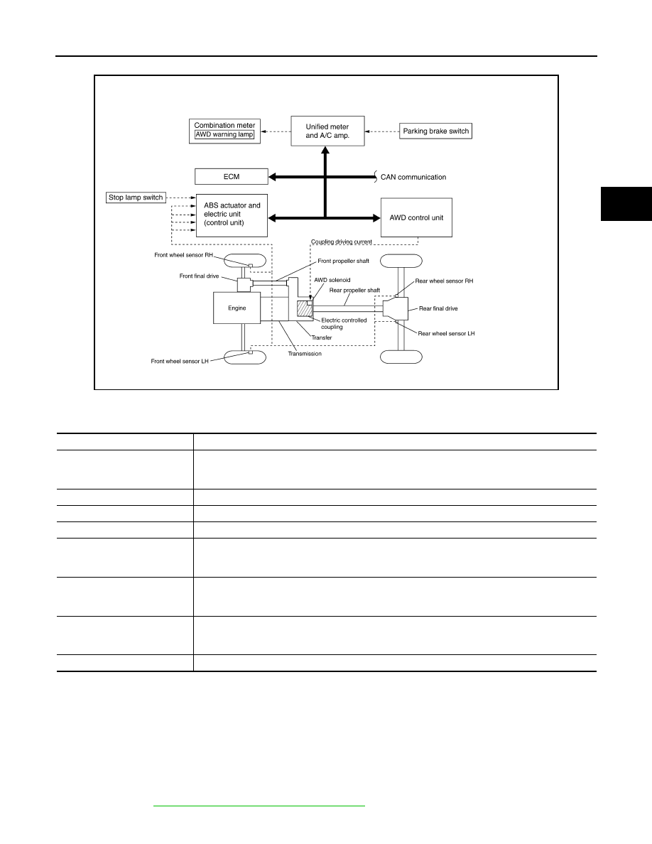
Schematic
INFOID:0000000001327433
COMPONENTS FUNCTION DESCRIPTION
CAN Communication
INFOID:0000000001327434
SYSTEM DESCRIPTION
CAN (Controller Area Network) is a serial communication line for real time application. It is an on-vehicle mul-
tiplex communication line with high data communication speed and excellent error detection ability. Many elec-
tronic control units are equipped onto a vehicle, and each control unit shares information and links with other
control units during operation (not independent). In CAN communication, control units are connected with 2
communication lines (CAN H line, CAN L line) allowing a high rate of information transmission with less wiring.
Each control unit transmits/receives data but selectively reads required data only.
For details, refer to
LAN-43, "CAN System Specification Chart"
.
SDIA2160E
Component parts
Function
AWD control unit
• Controls driving force distribution by signals from each sensor and switch from rear wheel driving
mode (0:100) to AWD mode (50:50).
• 2WD mode is available by fail-safe function if malfunction is detected in AWD system.
Wheel sensors
Detects wheel speed.
AWD solenoid
Controls electric controlled coupling by command current from AWD control unit.
Electric controlled coupling
Transmits driving force to front final drive.
AWD warning lamp
• Illuminates if malfunction is detected in electrical system of AWD system.
• There is 1 blink in 2 seconds if rotation difference of front wheels and rear wheels is large.
• There are 2 blinks in 1 second if load is still applied to driving parts.
ABS actuator and electric unit
(control unit)
Transmits the following signals via CAN communication to AWD control unit.
• Vehicle speed signal
• Stop lamp switch signal (brake signal)
ECM
Transmits the following signals via CAN communication to AWD control unit.
• Accelerator pedal position signal
• Engine speed signal
Unified meter and A/C amp.
Transmits conditions of parking brake switch via CAN communication to AWD control unit.
TF-14
< SERVICE INFORMATION >
TROUBLE DIAGNOSIS
TROUBLE DIAGNOSIS
Fail-Safe Function
INFOID:0000000001327435
• If any malfunction occurs in AWD electrical system, and control unit detects the malfunction, AWD warning
lamp on combination meter turns ON to indicate system malfunction.
• When AWD warning lamp is ON, vehicle changes to rear-wheel drive or shifting driving force-AWD (Front-
wheels still have some driving torque).
How to Perform Trouble Diagnosis
INFOID:0000000001327436
BASIC CONCEPT
• To perform trouble diagnosis, it is the most important to have understanding about vehicle systems (control
and mechanism) thoroughly.
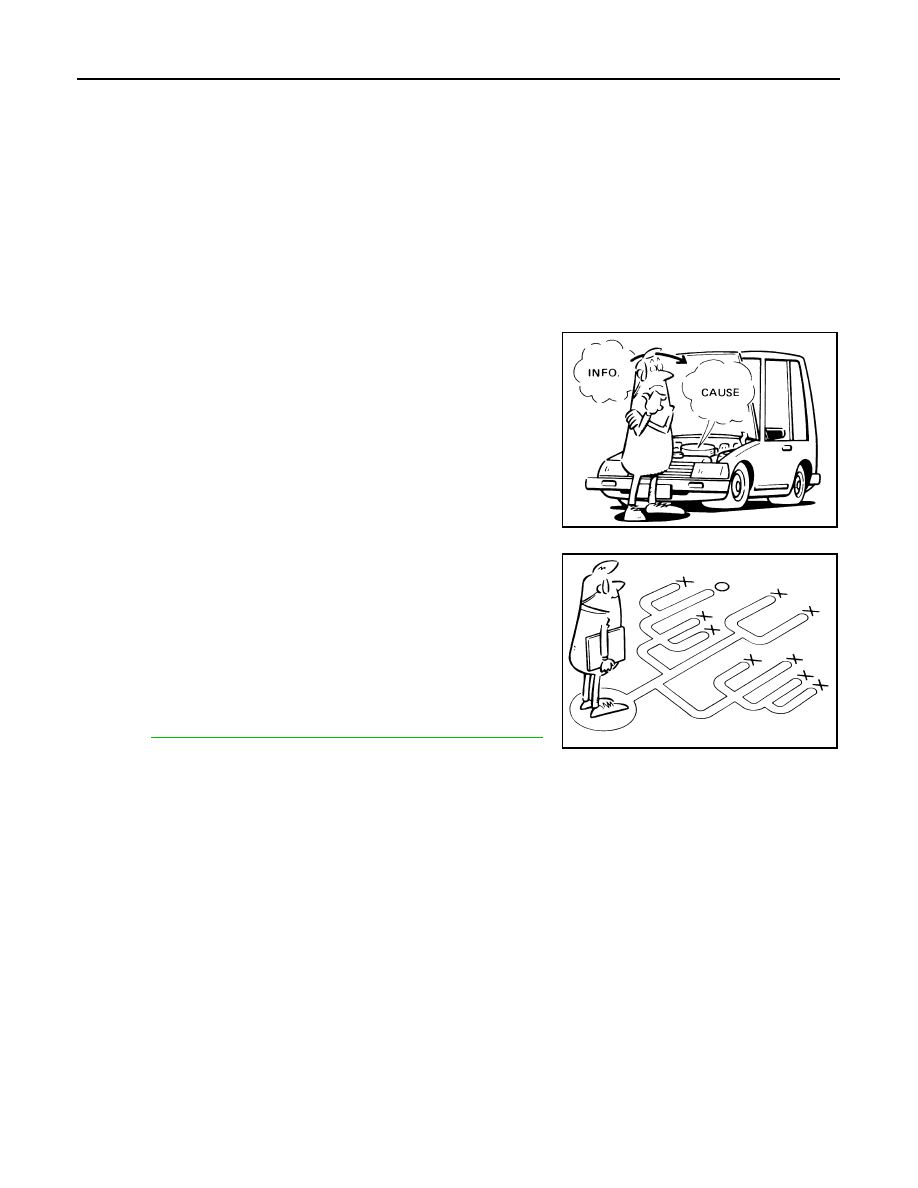
• It is also important to clarify customer complaints before inspec-
tion.
First of all, reproduce symptoms, and understand them fully.
Ask customer about his/her complaints carefully. In some cases, it
will be necessary to check symptoms by driving vehicle with cus-
tomer.
CAUTION:
Customers are not professional. It is dangerous to make an
easy guess like “maybe the customer means that...,” or
“maybe the customer mentions this symptom”.
• It is essential to check symptoms right from the beginning in order
to repair malfunctions completely.
For intermittent malfunctions, reproduce symptoms based on inter-
view with customer and past examples. Do not perform inspection
on ad hoc basis. Most intermittent malfunctions are caused by
poor contacts. In this case, it will be effective to shake suspected
harness or connector by hand. When repairing without any symp-
tom diagnosis, you cannot judge if malfunctions have actually been
eliminated.
• After completing diagnosis, always erase diagnostic memory.
TF-21, "CONSULT-III Function (ALL MODE AWD/4WD)"
• For intermittent malfunctions, move harness or harness connector
by hand. Then check for poor contact or reproduced open circuit.
SEF233G
SEF234G
Нет комментариевНе стесняйтесь поделиться с нами вашим ценным мнением.
Текст