Infiniti FX35 / FX45. Manual — part 233
IVIS (INFINITI VEHICLE IMMOBILIZER SYSTEM-NATS)
BL-199
< SERVICE INFORMATION >
C
D
E
F
G
H
J
K
L
M
A
B
BL
N
O
P
NG
>> Reinstall NATS antenna amp. correctly.
3.
CHECK KEY ID CHIP
Start engine with another registered ignition key or mechanical key.
Does the engine start?
YES
>>
Ignition key or mechanical key ID chip is malfunctioning.
• Replace the ignition key or mechanical key.
• Perform initialization with CONSULT-III.
For initialization, refer to “CONSULT-III Operation Manual NATS–IVIS/NVIS”.
NO
>> GO TO 4.
4.
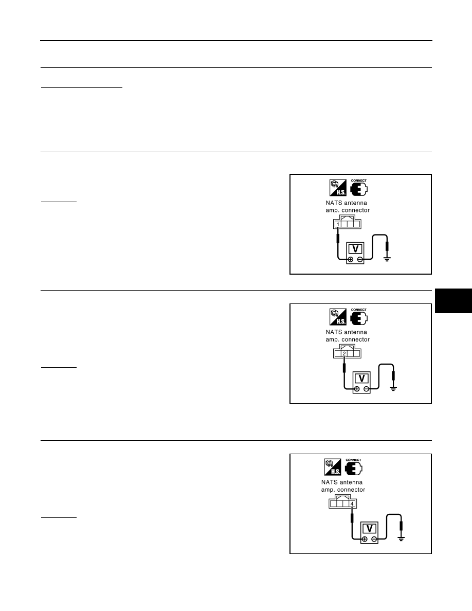
CHECK POWER SUPPLY FOR NATS ANTENNA AMP.
Check voltage between NATS antenna amp. connector M25 terminal 1 (L/R) and ground with CONSULT-III or
tester.
OK or NG
OK
>> GO TO 5.
NG
>> Check harness for open or short between NATS
antenna amp. and fuse.
5.
CHECK NATS ANTENNA AMP. SIGNAL LINE- 1
Check voltage between NATS antenna amp. connector M25 terminal 2 (G/B) and ground with analogue tester.
OK or NG
OK
>> GO TO 6.
NG
>> • Check harness for open or short between NATS
antenna amp. and BCM.
NOTE:
If harness is OK, replace BCM, perform initialization
with CONSULT-III. For initialization, refer to “CONSULT-III Operation Manual NATS–IVIS/NVIS”.
6.
CHECK NATS ANTENNA AMP. SIGNAL LINE- 2
Check voltage between NATS antenna amp. connector M25 terminal 4 (BR) and ground with analogue tester.
OK or NG
OK
>> GO TO 7.
NG
>> • Check harness for open or short between NATS
antenna amp. and BCM.
NOTE:
If harness is OK, replace BCM, perform initialization
with CONSULT-III. For initialization, refer to “CONSULT-III Operation Manual NATS–IVIS/NVIS”.
1 (L/R) – Ground
: Battery voltage
PIIA6145E
Before inserting mechanical key in ignition knob
Voltage: 0V
Just after inserting mechanical key in ignition knob
: Pointer of tester should move.
PIIA6146E
Before inserting mechanical key in ignition knob
Voltage: 0V
Just after inserting mechanical key in ignition knob
: Pointer of tester should move.
PIIA6147E
BL-200
< SERVICE INFORMATION >
IVIS (INFINITI VEHICLE IMMOBILIZER SYSTEM-NATS)
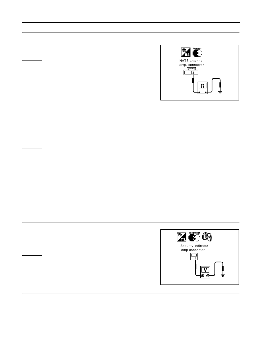
7.
CHECK NATS ANTENNA AMP. GROUND LINE CIRCUIT
1.
Turn ignition switch OFF.
2.
Check continuity between NATS antenna amp. connector M25 terminal 3 (B) and ground.
OK or NG
OK
>> NATS antenna amp. is malfunctioning.
NG
>> • Check harness for open or short between NATS
antenna amp. and ground.
NOTE:
If harness is OK, replace BCM, perform initialization
with CONSULT-III. For initialization, refer to “CON-
SULT-III Operation Manual NATS–IVIS/NVIS”.
Diagnosis Procedure 6
INFOID:0000000001327939
“SECURITY INDICATOR LAMP DOES NOT LIGHT UP”
1.
CHECK FUSE
• Check 10A fuse [No.19, located in the fuse block (J/B)]
NOTE:
Refer to
BL-185, "Component Parts and Harness Connector Location"
OK or NG
OK
>> GO TO 2.
NG
>> Replace fuse.
2.
CHECK SECURITY INDICATOR LAMP
1.
Install 10A fuse [No.19, located in the fuse block (J/B)]
2.
Start engine and turn ignition switch OFF.
3.
Check the security indicator lamp lights up.
OK or NG
OK
>> Inspection END.
NG
>> GO TO 3.
3.
CHECK SECURITY INDICATOR LAMP POWER SUPPLY CIRCUIT
1.
Disconnect security indicator lamp connector.
2.
Check voltage between security indicator lamp connector M38
terminal 1 (R/W) and ground.
OK or NG
OK
>> GO TO 4.
NG
>> Check harness for open or short between fuse and
security indicator lamp.
4.
CHECK BCM FUNCTION
1.
Connect security indicator lamp connector.
2.
Disconnect BCM connector M3.
3 (B) – Ground
: Continuity should exist.
PIIA6148E
Security indicator lamp should light up.
1 (R/W) – Ground
: Battery voltage
PIIA6149E
IVIS (INFINITI VEHICLE IMMOBILIZER SYSTEM-NATS)
BL-201
< SERVICE INFORMATION >
C
D
E
F
G
H
J
K
L
M
A
B
BL
N
O
P
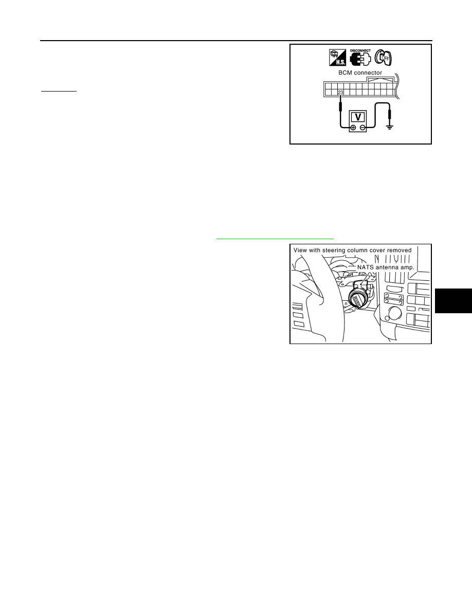
3.
Check voltage between BCM connector M3 terminal 23 (G/OR)
and ground.
OK or NG
OK
>>
BCM is malfunctioning.
• Replace BCM.
• Perform initialization with CONSULT-III.
• For initialization, refer to “CONSULT-III Operation
Manual NATS-IVIS/NVIS”.
NG
>>
Check the following.
• Harness for open or short between security indicator lamp and BCM.
• Indicator lamp condition
Removal and Installation NATS Antenna Amp
INFOID:0000000001327940
REMOVAL
CAUTION:
Before servicing SRS, turn ignition switch OFF, disconnect both battery cables and wait at least 3 min-
utes.
1.
Remove the steering column cover. Refer to
IP-11, "Removal and Installation"
2.
Disconnect the NATS antenna amp. connect, remove the screw
and NATS antenna amp.
INSTALLATION
Install in the reverse order of removal.
23 (G/OR) – Ground
: Battery voltage
PIIA6150E
PIIA6064E
BL-202
< SERVICE INFORMATION >
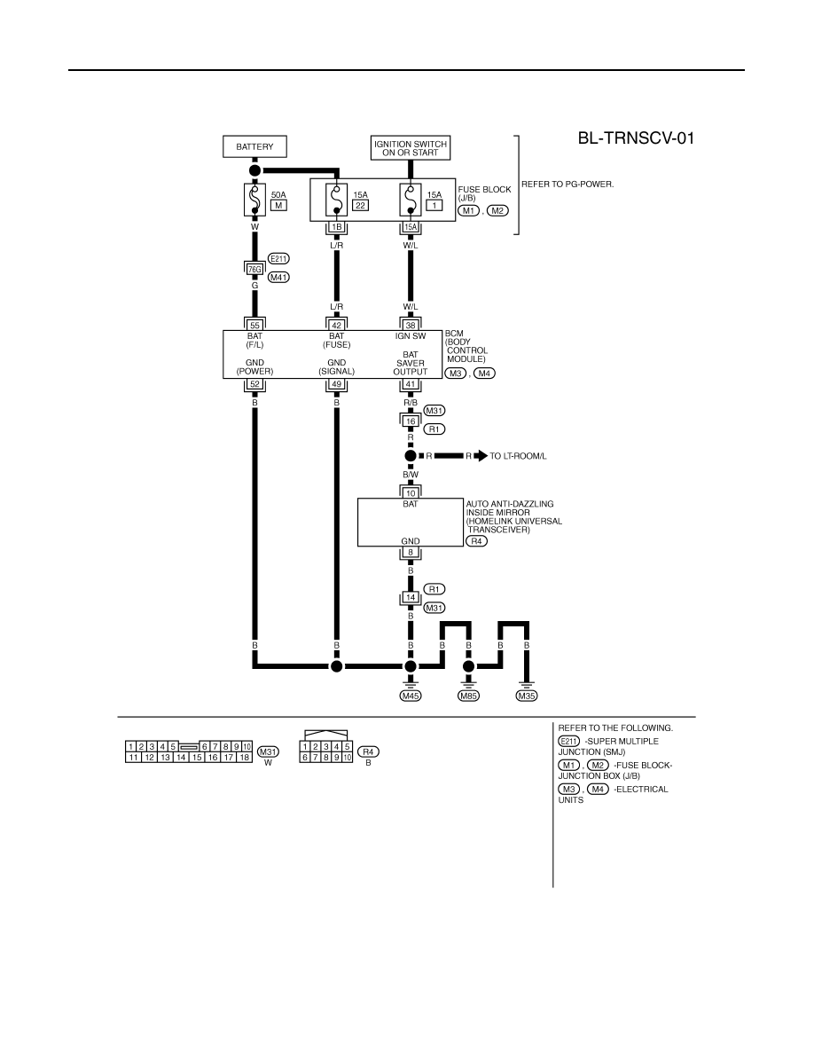
INTEGRATED HOMELINK TRANSMITTER
INTEGRATED HOMELINK TRANSMITTER
Wiring Diagram - TRNSCV -
INFOID:0000000001327941
Trouble Diagnosis
INFOID:0000000001327942
DIAGNOSTIC PROCEDURE
SYMPTOM: Transmitter Does Not Activate Receiver.
TIWM1680E
Нет комментариевНе стесняйтесь поделиться с нами вашим ценным мнением.
Текст