Infiniti FX35 / FX45. Manual — part 429
DTC P1572 ASCD BRAKE SWITCH
EC-477
< SERVICE INFORMATION >
[VQ35DE]
C
D
E
F
G
H
I
J
K
L
M
A
EC
N
P
O
Diagnosis Procedure
INFOID:0000000001326342
1.
CHECK OVERALL FUNCTION-I
With CONSULT-III
1.
Turn ignition switch ON.
2.
Select “BRAKE SW1” in “DATA MONITOR” mode with CONSULT-III.
3.
Check “BRAKE SW1” indication under the following conditions.
Without CONSULT-III
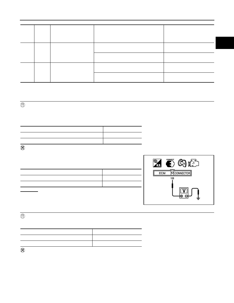
1.
Turn ignition switch ON.
2.
Check voltage between ECM terminal 108 and ground under the
following conditions.
OK or NG
OK
>> GO TO 2.
NG
>> GO TO 3.
2.
CHECK OVERALL FUNCTION-II
With CONSULT-III
Check “BRAKE SW2” indication in “DATA MONITOR” mode.
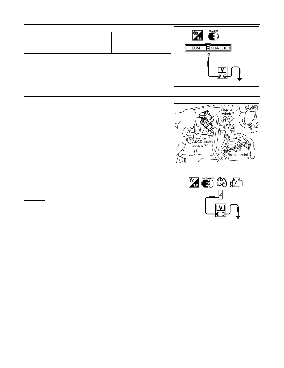
Without CONSULT-III
Check voltage between ECM terminal 101 and ground under the following conditions.
TER-
MI-
NAL
NO.
WIRE
COLOR
ITEM
CONDITION
DATA (DC Voltage)
101
P/L
Stop lamp switch
[Ignition switch: OFF]
• Brake pedal: Fully released
Approximately 0V
[Ignition switch: OFF]
• Brake pedal: Slightly depressed
BATTERY VOLTAGE
(11 - 14V)
108
SB
ASCD brake switch
[Ignition switch: ON]
• Brake pedal: Slightly depressed
Approximately 0V
[Ignition switch: ON]
• Brake pedal: Fully released
BATTERY VOLTAGE
(11 - 14V)
CONDITION
INDICATION
Brake pedal: Slightly depressed
OFF
Brake pedal: Fully released
ON
CONDITION
VOLTAGE
Brake pedal: Slightly depressed
Approximately 0V
Brake pedal: Fully released
Battery voltage
MBIB0061E
CONDITION
INDICATION
Brake pedal: Fully released
OFF
Brake pedal: Slightly depressed
ON
EC-478
< SERVICE INFORMATION >
[VQ35DE]
DTC P1572 ASCD BRAKE SWITCH
OK or NG
OK
>> GO TO 13.
NG
>> GO TO 8.
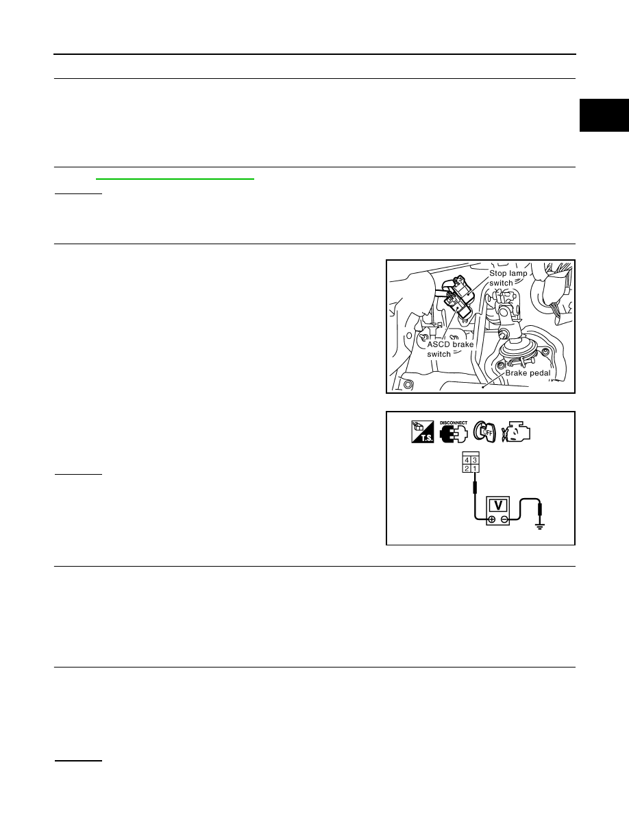
3.
CHECK ASCD BRAKE SWITCH POWER SUPPLY CIRCUIT
1.
Turn ignition switch OFF.
2.
Disconnect ASCD brake switch harness connector.
3.
Turn ignition switch ON.
4.
Check voltage between ASCD brake switch terminal 1 and
ground with CONSULT-III or tester.
OK or NG
OK
>> GO TO 5.
NG
>> GO TO 4.
4.
DETECT MALFUNCTIONING PART
Check the following.
• Fuse block (J/B) connector E201
• 10A fuse
• Harness for open or short between ASCD brake switch and fuse
>> Repair open circuit or short to ground or short to power in harness or connectors.
5.
CHECK ASCD BRAKE SWITCH INPUT SIGNAL CIRCUIT FOR OPEN AND SHORT
1.
Turn ignition switch OFF.
2.
Disconnect ECM harness connector.
3.
Check harness continuity between ECM terminal 108 and ASCD brake switch terminal 2.
Refer to Wiring Diagram.
4.
Also check harness for short to ground and short to power.
OK or NG
OK
>> GO TO 7.
NG
>> GO TO 6.
CONDITION
VOLTAGE
Brake pedal: Fully released
Approximately 0V
Brake pedal: Slightly depressed
Battery voltage
MBIB0060E
PBIB1605E
Voltage: Battery voltage
PBIB0857E
Continuity should exist.
DTC P1572 ASCD BRAKE SWITCH
EC-479
< SERVICE INFORMATION >
[VQ35DE]
C
D
E
F
G
H
I
J
K
L
M
A
EC
N
P
O
6.
DETECT MALFUNCTIONING PART
Check the following.
• Harness connectors E211, M41
• Harness for open or short between ECM and ASCD brake switch
>> Repair open circuit or short to ground or short to power in harness or connectors.
7.
CHECK ASCD BRAKE SWITCH
EC-480, "Component Inspection"
OK or NG
OK
>> GO TO 13.
NG
>> Replace ASCD brake switch.
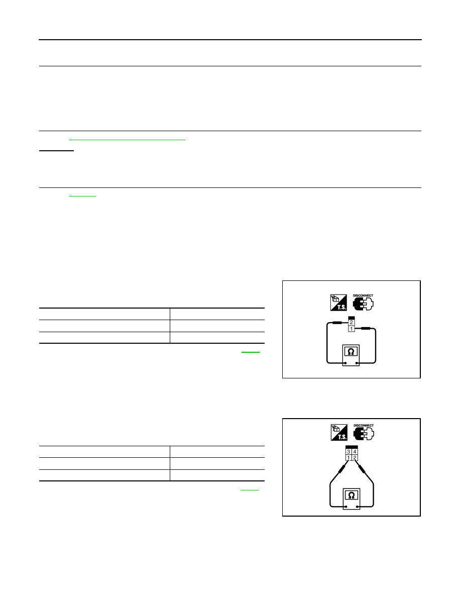
8.
CHECK STOP LAMP SWITCH POWER SUPPLY CIRCUIT
1.
Turn ignition switch OFF.
2.
Disconnect stop lamp switch harness connector.
3.
Check voltage between stop lamp switch terminal 1 and ground
with CONSULT-III or tester.
OK or NG
OK
>> GO TO 10.
NG
>> GO TO 9.
9.
DETECT MALFUNCTIONING PART
Check the following.
• Fuse block (J/B) connector E201
• 10A fuse
• Harness for open or short between stop lamp switch and battery
>> Repair open circuit or short to ground or short to power in harness or connectors.
10.
CHECK STOP LAMP SWITCH INPUT SIGNAL CIRCUIT FOR OPEN AND SHORT
1.
Disconnect ECM harness connector.
2.
Check harness continuity between ECM terminal 101 and stop lamp switch terminal 2.
Refer to Wiring Diagram.
3.
Also check harness for short to ground and short to power.
OK or NG
OK
>> GO TO 12.
PBIB1605E
Voltage: Battery voltage
PBIB1184E
Continuity should exist.
EC-480
< SERVICE INFORMATION >
[VQ35DE]
DTC P1572 ASCD BRAKE SWITCH
NG
>> GO TO 11.
11.
DETECT MALFUNCTIONING PART
Check the following.
• Harness connectors E211, M41
• Harness for open or short between ECM and stop lamp switch
>> Repair open circuit or short to ground or short to power in harness or connectors.
12.
CHECK STOP LAMP SWITCH
EC-480, "Component Inspection"
OK or NG
OK
>> GO TO 13.
NG
>> Replace stop lamp switch.
13.
CHECK INTERMITTENT INCIDENT
>> INSPECTION END
Component Inspection
INFOID:0000000001326343
ASCD BRAKE SWITCH
1.
Turn ignition switch OFF.
2.
Disconnect ASCD brake switch harness connector.
3.
Check continuity between ASCD brake switch terminals 1 and 2
under the following conditions.
If NG, adjust ASCD brake switch installation, refer to
perform step 3 again.
STOP LAMP SWITCH
1.
Turn ignition switch OFF.
2.
Disconnect stop lamp switch harness connector.
3.
Check continuity between stop lamp switch terminals 1 and 2
under the following conditions.
If NG, adjust stop lamp switch installation, refer to
, and
perform step 3 again.
Condition
Continuity
Brake pedal: Fully released
Should exist
Brake pedal: Slightly depressed
Should not exist
SEC023D
Condition
Continuity
Brake pedal: Fully released
Should not exist
Brake pedal: Slightly depressed
Should exist
PBIB1185E
Нет комментариевНе стесняйтесь поделиться с нами вашим ценным мнением.
Текст