Infiniti FX35 / FX45. Manual — part 428
DTC P1572 ICC BRAKE SWITCH
EC-473
< SERVICE INFORMATION >
[VQ35DE]
C
D
E
F
G
H
I
J
K
L
M
A
EC
N
P
O
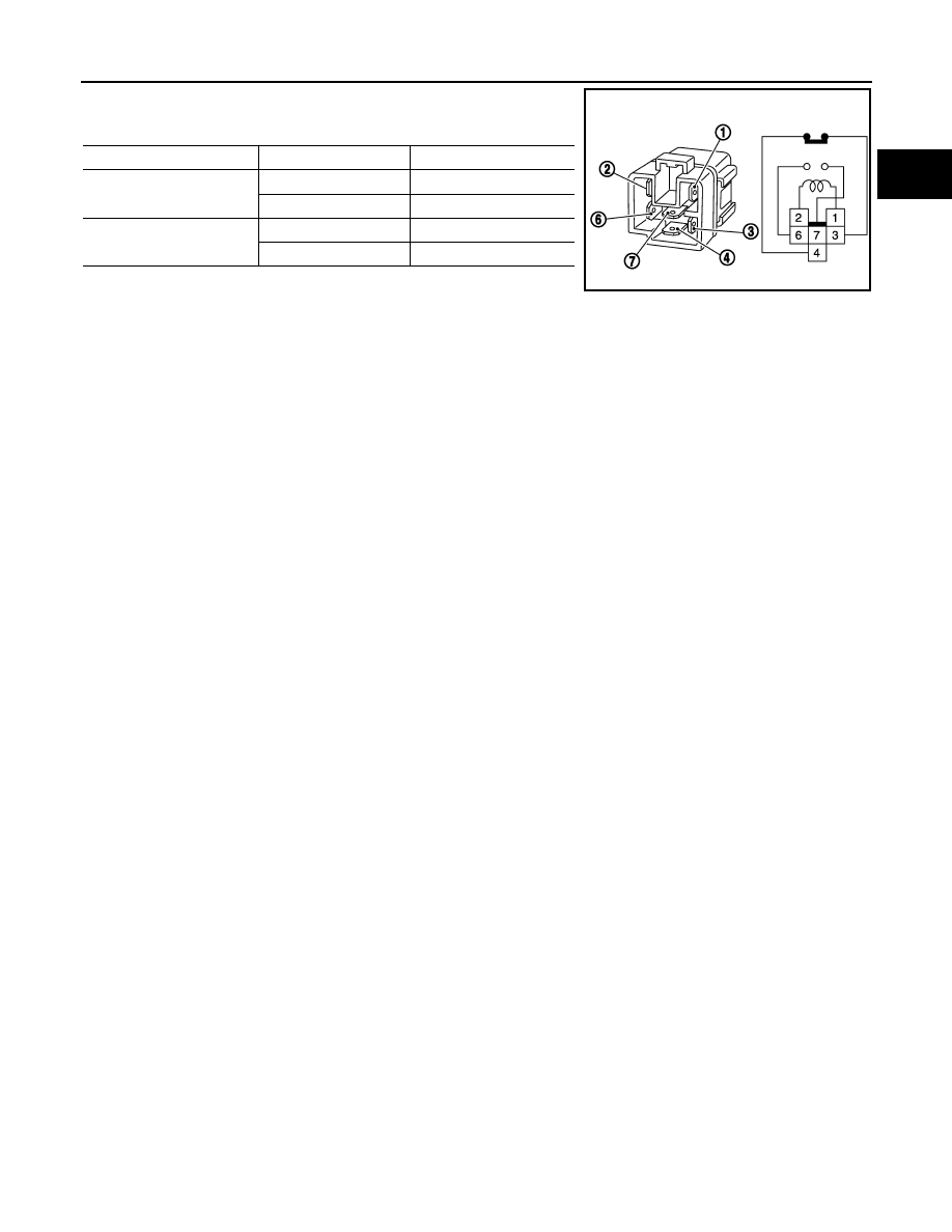
2.
Check continuity between relay terminals 3 and 4, 6 and 7 under
the following conditions.
3.
If NG, replace ICC brake hold relay.
Condition
Between terminals
Continuity
12V direct current supply
between terminals 1 and 2
3 and 4
Should not exist
6 and 7
Should exist
No current supply
3 and 4
Should exist
6 and 7
Should not exist
MBIB0063E
EC-474
< SERVICE INFORMATION >
[VQ35DE]
DTC P1572 ASCD BRAKE SWITCH
DTC P1572 ASCD BRAKE SWITCH
Component Description
INFOID:0000000001326337
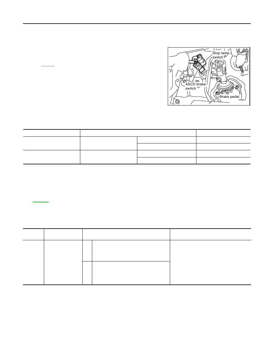
When the brake pedal is depressed, ASCD brake switch is turned
OFF and stop lamp switch is turned ON. ECM detects the state of
the brake pedal by this input of two kinds (ON/OFF signal).
Refer to
CONSULT-III Reference Value in Data Monitor Mode
INFOID:0000000001326338
Specification data are reference values.
On Board Diagnosis Logic
INFOID:0000000001326339
• This self-diagnosis has the one trip detection logic.
• The MIL will not light up for this self-diagnosis.
NOTE:
• If DTC P1572 is displayed with DTC P0605, first perform the trouble diagnosis for DTC P0605. Refer
• This self-diagnosis has the one trip detection logic. When malfunction A is detected, DTC is not
stored in ECM memory. And in that case, 1st trip DTC and 1st trip freeze frame data are displayed.
1st trip DTC is erased when ignition switch OFF. And even when malfunction A is detected in two
consecutive trips, DTC is not stored in ECM memory.
DTC Confirmation Procedure
INFOID:0000000001326340
CAUTION:
Always drive vehicle at a safe speed.
NOTE:
• If DTC Confirmation Procedure has been previously conducted, always turn ignition switch OFF and wait at
least 10 seconds before conducting the next test.
• Procedure for malfunction B is not described here. It takes extremely long time to complete procedure for
malfunction B. By performing procedure for malfunction A, the incident that causes malfunction B can be
detected.
PBIB1605E
MONITOR ITEM
CONDITION
SPECIFICATION
BRAKE SW1
(ASCD brake switch)
• Ignition switch: ON
Brake pedal: Fully released
ON
Brake pedal: Slightly depressed
OFF
BRAKE SW2
(Stop lamp switch)
• Ignition switch: ON
Brake pedal: Fully released
OFF
Brake pedal: Slightly depressed
ON
DTC No.
Trouble Diagnosis
Name
DTC Detecting Condition
Possible Cause
P1572
1572
ASCD brake switch
A)
When the vehicle speed is above 30km/h (19
MPH), ON signals from the stop lamp switch
and the ASCD brake switch are sent to ECM
at the same time.
• Harness or connectors
(Stop lamp switch circuit is shorted.)
• Harness or connectors
(ASCD brake switch circuit is shorted.)
• Stop lamp switch
• ASCD brake switch
• Incorrect stop lamp switch installation
• Incorrect ASCD brake switch installation
• ECM
B)
ASCD brake switch signal is not sent to ECM
for extremely long time while the vehicle is
driving

DTC P1572 ASCD BRAKE SWITCH
EC-475
< SERVICE INFORMATION >
[VQ35DE]
C
D
E
F
G
H
I
J
K
L
M
A
EC
N
P
O
TESTING CONDITION:
Steps 4 and 5 may be conducted with the drive wheels lifted in the shop or by driving the vehicle. If a
road test is expected to be easier, it is unnecessary to lift the vehicle.
WITH CONSULT-III
1.
Start engine.
2.
Select “DATA MONITOR” mode with CONSULT-III.
3.
Press MAIN switch and make sure that CRUISE indicator lights up.
4.
Drive the vehicle for at least 5 consecutive seconds under the following condition.
5.
Check 1st trip DTC.
If 1st trip DTC is detected, go to
If 1st trip DTC is not detected, go to the following step.
6.
Drive the vehicle for at least 5 consecutive seconds under the following condition.
7.
Check 1st trip DTC.
8.
If 1st trip DTC is detected, go to
WITH GST
Follow the procedure “WITH CONSULT-III” above.
VHCL SPEED SE
More than 30 km/h (19 MPH)
Selector lever
Suitable position
VHCL SPEED SE
More than 30 km/h (19 MPH)
Selector lever
Suitable position
Driving location
Depress the brake pedal for more than
five seconds so as not to come off from
the above-mentioned vehicle speed.
EC-476
< SERVICE INFORMATION >
[VQ35DE]
DTC P1572 ASCD BRAKE SWITCH
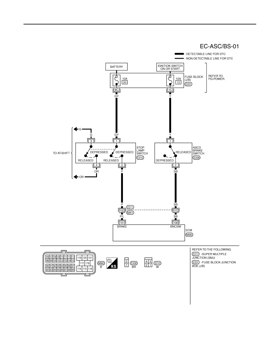
Wiring Diagram
INFOID:0000000001326341
Specification data are reference values and are measured between each terminal and ground.
CAUTION:
Do not use ECM ground terminals when measuring input/output voltage. Doing so may result in dam-
age to the ECM's transistor. Use a ground other than ECM terminals, such as the ground.
TBWM1402E
Нет комментариевНе стесняйтесь поделиться с нами вашим ценным мнением.
Текст