Infiniti FX35 / FX45. Manual — part 450
FUEL PUMP
EC-561
< SERVICE INFORMATION >
[VQ35DE]
C
D
E
F
G
H
I
J
K
L
M
A
EC
N
P
O
• Harness for open or short between IPDM E/R and ECM
>> Repair open circuit or short to ground or short to power in harness or connectors.
5.
CHECK FUEL PUMP POWER SUPPLY CIRCUIT-III
1.
Turn ignition switch OFF.
2.
Reconnect all harness connectors disconnected.
3.
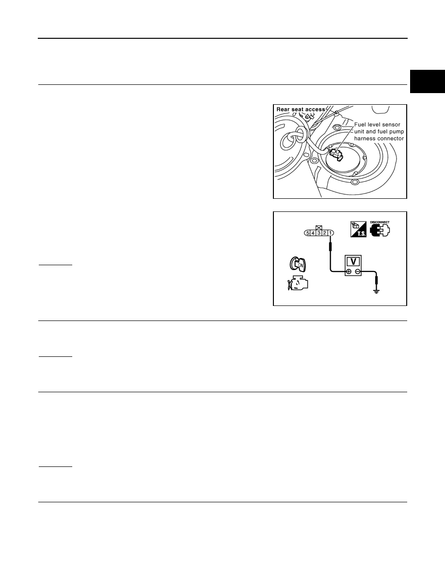
Disconnect “fuel level sensor unit and fuel pump” harness con-
nector.
4.
Turn ignition switch ON.
5.
Check voltage between “fuel level sensor unit and fuel pump”
terminal 1 and ground with CONSULT-III or tester.
OK or NG
OK
>> GO TO 9.
NG
>> GO TO 6.
6.
CHECK 15A FUSE
1.
Turn ignition switch OFF.
2.
Disconnect 15A fuse.
3.
Check 15A fuse.
OK or NG
OK
>> GO TO 7.
NG
>> Replace fuse.
7.
CHECK FUEL PUMP POWER SUPPLY CIRCUIT-IV
1.
Disconnect IPDM E/R harness connector E8.
2.
Check harness continuity between IPDM E/R terminal 39 and “fuel level sensor unit and fuel pump” termi-
nal 1.
Refer to Wiring Diagram.
3.
Also check harness for short to ground and short to power.
OK or NG
OK
>> GO TO 11.
NG
>> GO TO 8.
8.
DETECT MALFUNCTIONING PART
Check the following.
• Harness connectors E206, B6
• Harness for open or short between IPDM E/R and “fuel level sensor unit and fuel pump”
>> Repair open circuit or short to ground or short to power in harness or connectors.
PBIB1572E
Voltage:
Battery voltage should exist for 1 second
after ignition switch is turned ON.
PBIB0795E
Continuity should exist.
EC-562
< SERVICE INFORMATION >
[VQ35DE]
FUEL PUMP
9.
CHECK FUEL PUMP GROUND CIRCUIT FOR OPEN AND SHORT
1.
Check harness continuity between “fuel level sensor unit and fuel pump” terminal 3 and ground.
Refer to Wiring Diagram.
2.
Also check harness for short to power.
OK or NG
OK
>> GO TO 10.
NG
>> Repair open circuit or short to power in harness or connectors.
10.
CHECK FUEL PUMP
EC-1159, "Component Inspection"
.
OK or NG
OK
>> GO TO 11.
NG
>> Replace “fuel level sensor unit and fuel pump”.
11.
CHECK INTERMITTENT INCIDENT
OK or NG
OK
>> Replace IPDM E/R. Refer to
NG
>> Repair or replace harness or connectors.
Component Inspection
INFOID:0000000001326448
FUEL PUMP
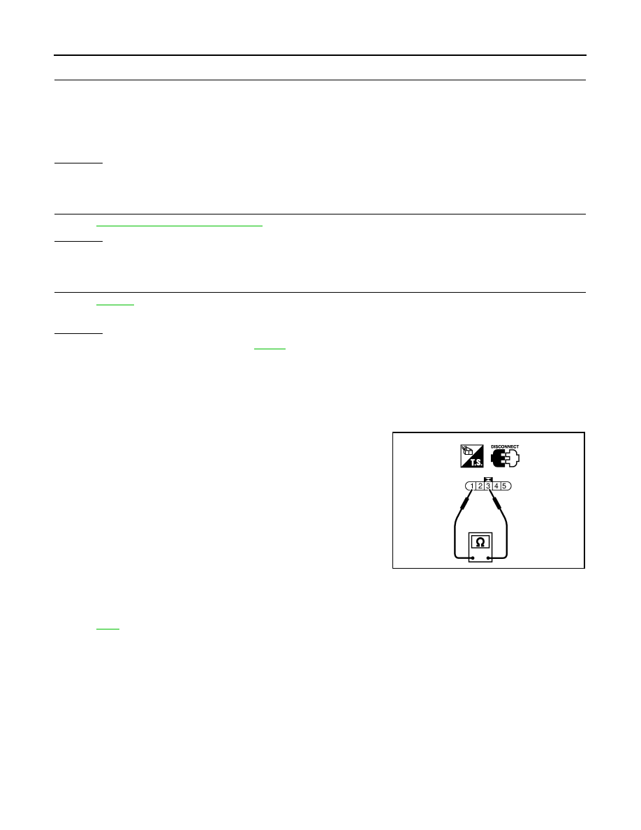
1.
Disconnect “fuel level sensor unit and fuel pump” harness connector.
2.
Check resistance between “fuel level sensor unit and fuel pump”
terminals 1 and 3.
Removal and Installation
INFOID:0000000001326449
FUEL PUMP
Continuity should exist.
Resistance: 0.2 - 5.0
Ω
[at 25
°
C (77
°
F)]
SEC918C

ICC BRAKE SWITCH
EC-563
< SERVICE INFORMATION >
[VQ35DE]
C
D
E
F
G
H
I
J
K
L
M
A
EC
N
P
O
ICC BRAKE SWITCH
Component Description
INFOID:0000000001326450
When the brake pedal is depressed, ICC brake switch is turned OFF
and stop lamp switch is turned ON. ECM detects the state of the
brake pedal by this input of two kinds (ON/OFF signal)
Refer to
CONSULT-III Reference Value in Data Monitor Mode
INFOID:0000000001326451
Specification data are reference values.
PBIB1539E
MONITOR ITEM
CONDITION
SPECIFICATION
BRAKE SW1
(ICC brake switch)
• Ignition switch: ON
• Brake pedal: Fully released
ON
• Brake pedal: Slightly depressed
OFF
BRAKE SW2
(Stop lamp switch)
• Ignition switch: ON
• Brake pedal: Fully released
OFF
• Brake pedal: Slightly depressed
ON
EC-564
< SERVICE INFORMATION >
[VQ35DE]
ICC BRAKE SWITCH
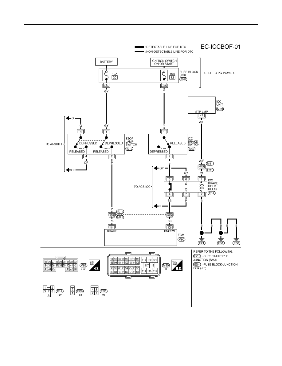
Wiring Diagram
INFOID:0000000001326452
Specification data are reference values and are measured between each terminal and ground.
CAUTION:
Do not use ECM ground terminals when measuring input/output voltage. Doing so may result in dam-
age to the ECM's transistor. Use a ground other than ECM terminals, such as the ground.
TBWM1410E
Нет комментариевНе стесняйтесь поделиться с нами вашим ценным мнением.
Текст