Infiniti FX35 / FX45. Manual — part 449
FUEL INJECTOR
EC-557
< SERVICE INFORMATION >
[VQ35DE]
C
D
E
F
G
H
I
J
K
L
M
A
EC
N
P
O
3.
Check harness continuity between fuel injector terminal 2 and ECM terminals 21, 22, 23, 40, 41, 42.
Refer to Wiring Diagram.
4.
Also check harness for short to ground and short to power.
OK or NG
OK
>> GO TO 10.
NG
>> GO TO 9.
9.
DETECT MALFUNCTIONING PART
Check the following.
• Harness connectors F251, F50
• Harness for open or short between fuel injector and ECM
>> Repair open circuit or short to ground or short to power in harness or connectors.
10.
CHECK FUEL INJECTOR
EC-557, "Component Inspection"
OK or NG
OK
>> GO TO 11.
NG
>> Replace malfunctioning fuel injector.
11.
CHECK INTERMITTENT INCIDENT
>> INSPECTION END
Component Inspection
INFOID:0000000001326442
FUEL INJECTOR
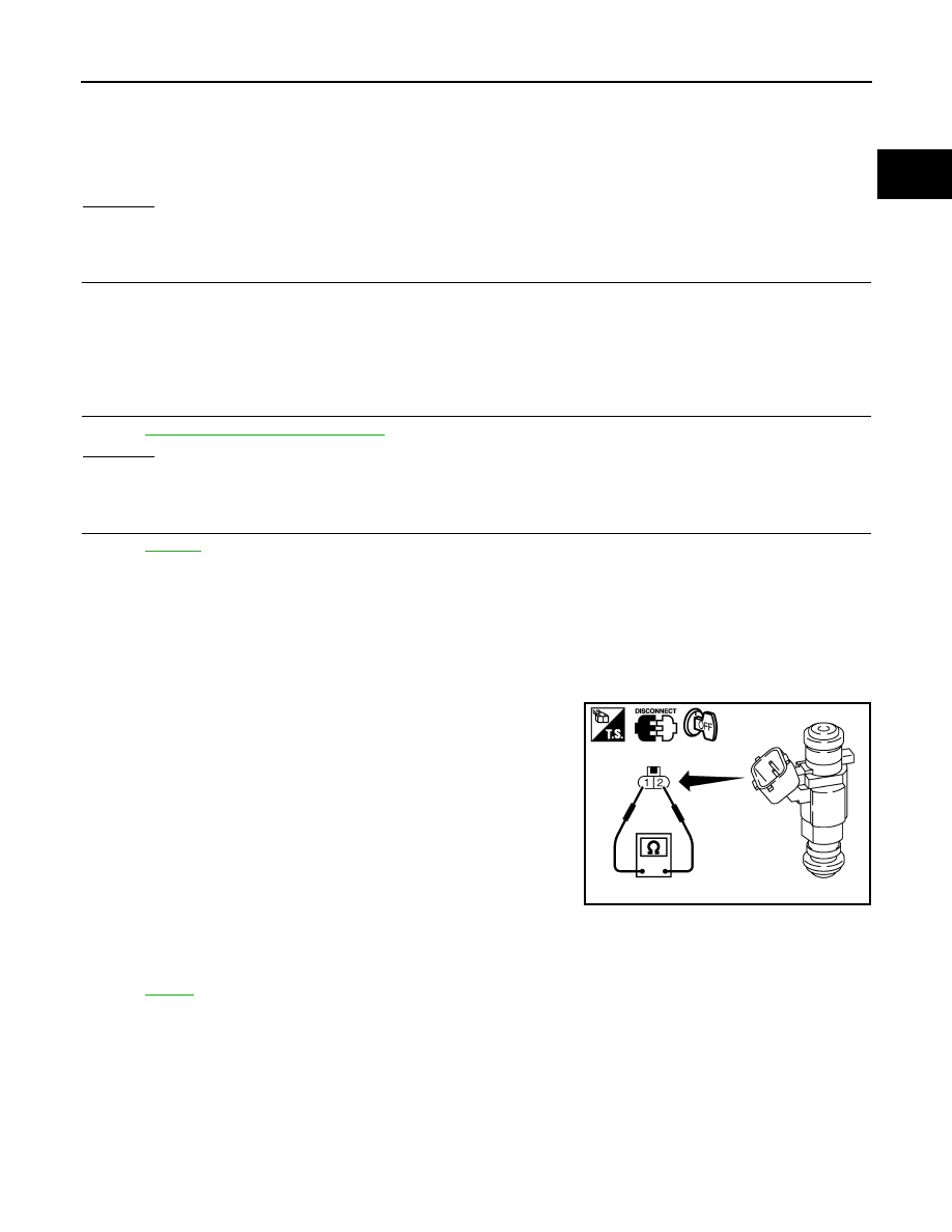
1.
Disconnect fuel injector harness connector.
2.
Check resistance between terminals as shown in the figure.
Removal and Installation
INFOID:0000000001326443
FUEL INJECTOR
Continuity should exist.
Resistance: 11.1 - 14.5
Ω
[at 10 - 60
°
C (50 - 140
°
F)]
PBIB1727E
EC-558
< SERVICE INFORMATION >
[VQ35DE]
FUEL PUMP
FUEL PUMP
Description
INFOID:0000000001326444
SYSTEM DESCRIPTION
*: ECM determines the start signal status by the signals of engine speed and battery voltage.
The ECM activates the fuel pump for several seconds after the ignition switch is turned ON to improve engine
start ability. If the ECM receives a engine speed signal from the camshaft position sensor (PHASE), it knows
that the engine is rotating, and causes the pump to operate. If the engine speed signal is not received when
the ignition switch is ON, the engine stalls. The ECM stops pump operation and prevents battery discharging,
thereby improving safety. The ECM does not directly drive the fuel pump. It controls the ON/OFF fuel pump
relay, which in turn controls the fuel pump.
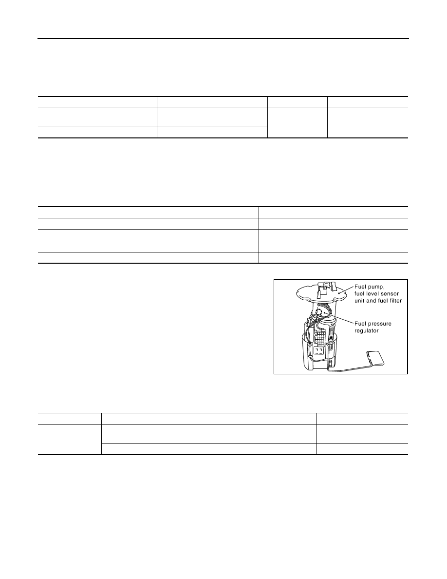
COMPONENT DESCRIPTION
A turbine type design fuel pump is used in the fuel tank.
CONSULT-III Reference Value in Data Monitor Mode
INFOID:0000000001326445
Specification data are reference values.
Sensor
Input Signal to ECM
ECM Function
Actuator
Crankshaft position sensor (POS)
Camshaft position sensor (PHASE)
Engine speed*
Fuel pump control
Fuel pump relay
Battery
Battery voltage*
Condition
Fuel pump operation
Ignition switch is turned to ON.
Operates for 1 second.
Engine running and cranking
Operates.
When engine is stopped
Stops in 1.5 seconds.
Except as shown above
Stops.
PBIB1569E
MONITOR ITEM
CONDITION
SPECIFICATION
FUEL PUMP RLY
• For 1 second after turning ignition switch ON
• Engine running or cranking
ON
• Except above conditions
OFF
FUEL PUMP
EC-559
< SERVICE INFORMATION >
[VQ35DE]
C
D
E
F
G
H
I
J
K
L
M
A
EC
N
P
O
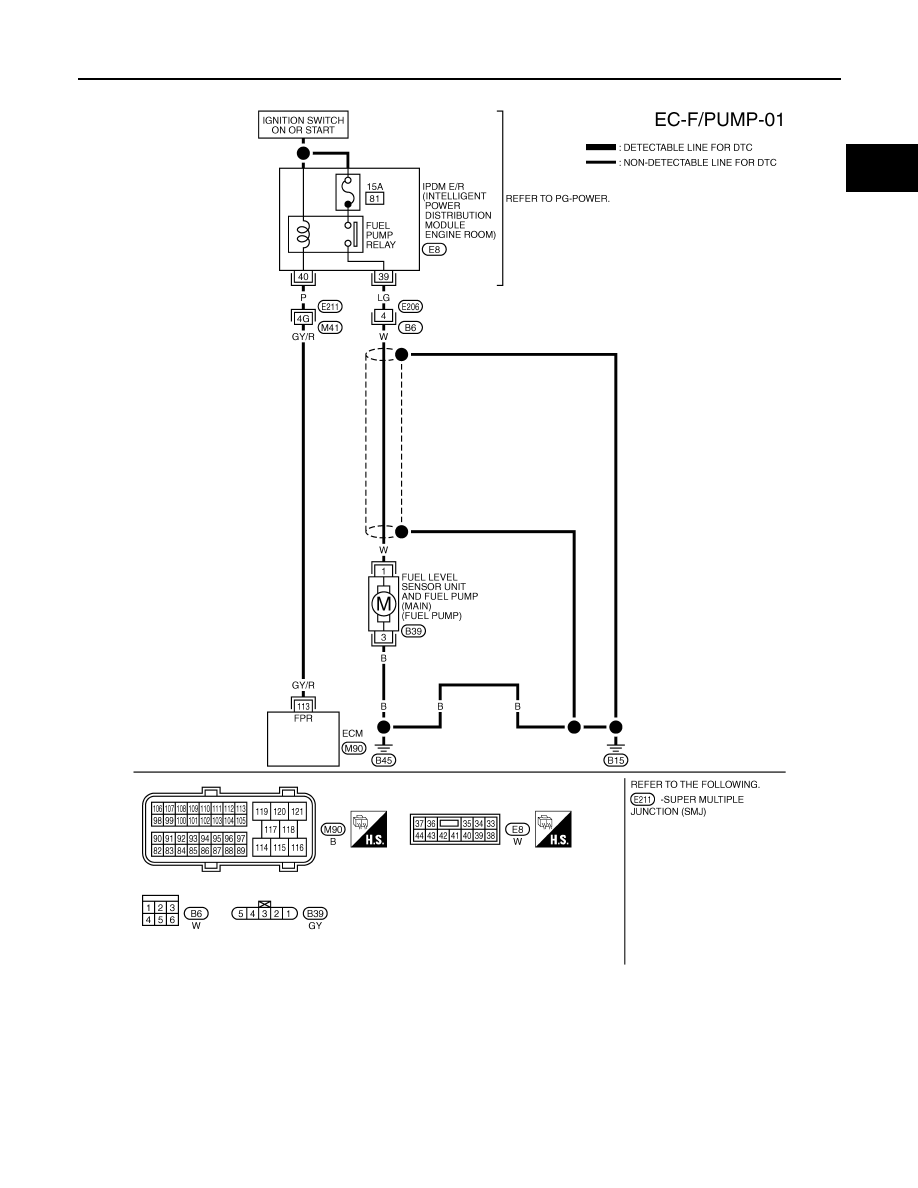
Wiring Diagram
INFOID:0000000001326446
Specification data are reference values and are measured between each terminal and ground.
CAUTION:
Do not use ECM ground terminals when measuring input/output voltage. Doing so may result in dam-
age to the ECM's transistor. Use a ground other than ECM terminals, such as the ground.
TBWM1409E
EC-560
< SERVICE INFORMATION >
[VQ35DE]
FUEL PUMP
Diagnosis Procedure
INFOID:0000000001326447
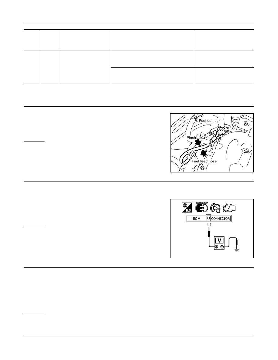
1.
CHECK OVERALL FUNCTION
1.
Turn ignition switch ON.
2.
Pinch fuel feed hose with two fingers.
OK or NG
OK
>> INSPECTION END
NG
>> GO TO 2.
2.
CHECK FUEL PUMP POWER SUPPLY CIRCUIT-I
1.
Turn ignition switch OFF.
2.
Disconnect ECM harness connector.
3.
Turn ignition switch ON.
4.
Check voltage between ECM terminal 113 and ground with
CONSULT-III or tester.
OK or NG
OK
>> GO TO 5.
NG
>> GO TO 3.
3.
CHECK FUEL PUMP POWER SUPPLY CIRCUIT-II
1.
Turn ignition switch OFF.
2.
Disconnect IPDM E/R harness connector E8.
3.
Check harness continuity between IPDM E/R terminal 40 and ECM terminal 113.
Refer to Wiring Diagram.
4.
Also check harness for short to ground and short to power.
OK or NG
OK
>> GO TO 11.
NG
>> GO TO 4.
4.
DETECT MALFUNCTIONING PART
Check the following.
• Harness connectors E211, M41
TER-
MI-
NAL
NO.
WIRE
COLOR
ITEM
CONDITION
DATA (DC Voltage)
113
GY/R
Fuel pump relay
[Ignition switch: ON]
• For 1 second after turning ignition switch ON
[Engine is running]
0 - 1.5V
[Ignition switch: ON]
• More than 1 second after turning ignition
switch ON
BATTERY VOLTAGE
(11 - 14V)
Fuel pressure pulsation should be felt on the fuel feed
hose for 1 second after ignition switch is turned ON.
PBIB1612E
Voltage: Battery voltage
PBIB1187E
Continuity should exist.
Нет комментариевНе стесняйтесь поделиться с нами вашим ценным мнением.
Текст