Infiniti FX35 / FX45. Manual — part 963
ROAD WHEEL TIRE ASSEMBLY
WT-9
< SERVICE INFORMATION >
C
D
F
G
H
I
J
K
L
M
A
B
WT
N
O
P
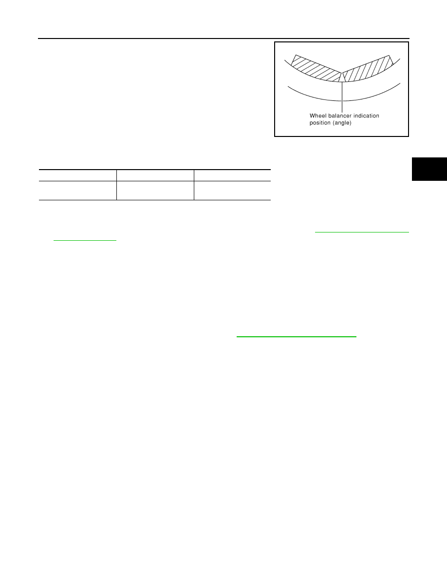
d.
If calculated balance weight value exceeds 50 g (1.76 oz), install
two balance weight sheets in line with each other as shown in
the figure.
CAUTION:
Do not install one balance weight sheet on top of another.
3.
Start tire balance machine again.
4.
Install drive-in balance weight on inner side of road wheel in the
tire balance machine indication position (angle).
CAUTION:
Do not install more than two balance weights.
5.
Start tire balance machine. Make sure that inner and outer resid-
ual unbalance values are 5 g (0.2 oz) each or below.
6.
If either residual unbalance value exceeds 5 g (0.2 oz), repeat installation procedures.
Tire Rotation
INFOID:0000000001327575
1.
Follow the maintenance schedule for tire rotation service intervals. Refer to
2.
Do not include the spare tire when rotating the tires.
3.
When installing the wheel, tighten wheel nuts to the specified torque.
CAUTION:
• When installing wheels, tighten them diagonally by dividing the work two to three times in order
to prevent the wheels from developing any distortion.
• Be careful not to tighten wheel nut at torque exceeding the criteria for preventing strain of disc
rotor.
4.
Perform the ID registration, after tire rotation. Refer to
WT-19, "ID Registration Procedure"
.
Wheel balance
Dynamic (At rim flange)
Static (At rim flange)
Maximum allowable un-
balance
5 g (0.2 oz) (one side)
20 g (0.7 oz)
SMA056D
Wheel nuts
: 108 N·m (11 kg-m, 80 ft-lb)
WT-10
< SERVICE INFORMATION >
TIRE PRESSURE MONITORING SYSTEM
TIRE PRESSURE MONITORING SYSTEM
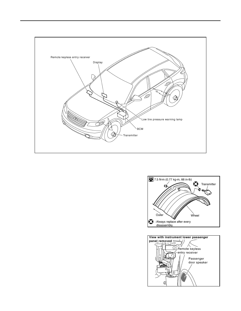
System Component
INFOID:0000000001327576
System Description
INFOID:0000000001327577
TRANSMITTER
A sensor-transmitter integrated with a valve is installed on a wheel,
and transmits a detected air pressure signal in the form of a radio
wave.
REMOTE KEYLESS ENTRY RECEIVER
The remote keyless entry receiver receives the air pressure signal
transmitted by the transmitter in each wheel.
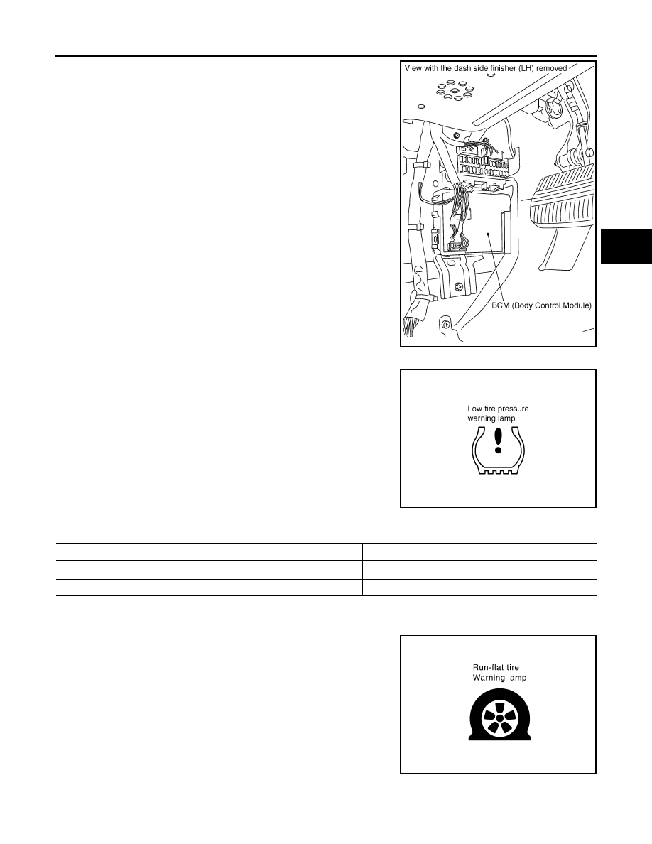
BCM (BODY CONTROL MODULE)
SEIA0599E
SEIA0521E
SEIA0431E
TIRE PRESSURE MONITORING SYSTEM
WT-11
< SERVICE INFORMATION >
C
D
F
G
H
I
J
K
L
M
A
B
WT
N
O
P
The BCM reads the air pressure signal received by the remote key-
less entry receiver, and controls the low tire pressure warning lamp
and the buzzer operations. It also has a judgment function to detect
a system malfunction.
LOW TIRE PRESSURE WARNING LAMP
The combination meter receives tire pressure status from the BCM
using CAN communication. When a low tire pressure condition is
sensed by the BCM, the combination meter low tire pressure warn-
ing lamp is activated.
Low Tire pressure Warning Lamp Indication
Note 1: Standard air pressure is for 220 kpa (2.2 kg/cm
2
, 32 psi) vehicles.
RUN-FLAT TIRE WARNING LAMP
The combination meter receives tire pressure status from the BCM
using CAN communication. When a low tire pressure condition is
sensed by the BCM, the combination meter run-frat tire warning
lamp and buzzer are activated.
Run-Flat Tire Warning Lamp Indication
SEIA0591E
SEIA0434E
Condition
Warning lamp
Less than 173 kPa (1.8 kg/cm
2
, 25 psi) [Note 1]
ON
Low tire pressure warning system malfunction [Other diagnostic item]
Warning lamp flashes 1 min, then turns ON
SEIA0792E
WT-12
< SERVICE INFORMATION >
TIRE PRESSURE MONITORING SYSTEM
Note 1: Standard air pressure is for 220 kpa (2.2 kg/cm
2
, 32 psi) vehicles.
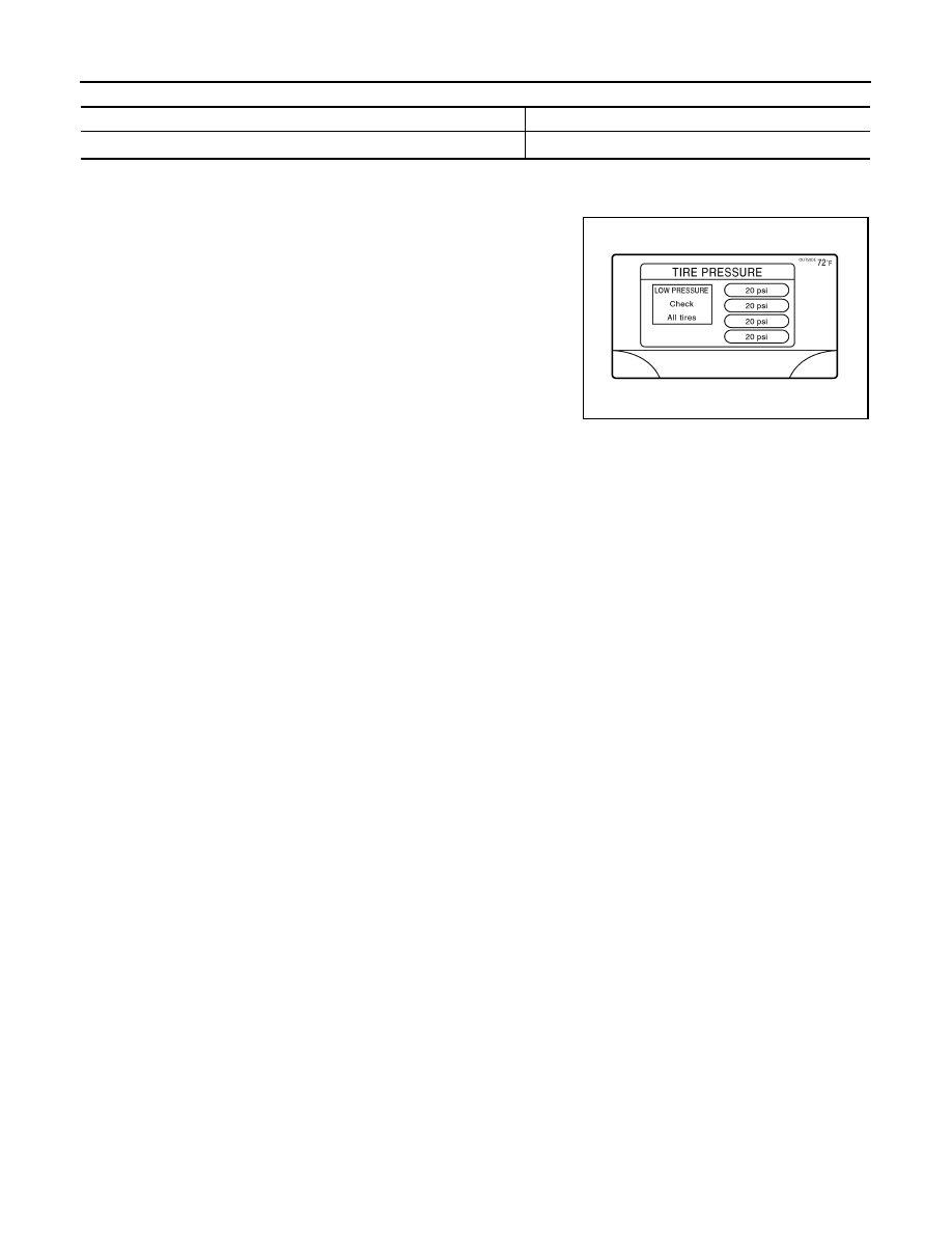
DISPLAY UNIT
Displays the air pressure of each tire.
• After the ignition switch is turned ON, the pressure values are not
displayed until the data of each wheel stabilizes.
Condition
Warning lamp
Less than 86 kPa (0.88 kg/cm
2
, 12.5 psi) [Note 1]
ON
JPEIC0024GB
Нет комментариевНе стесняйтесь поделиться с нами вашим ценным мнением.
Текст