Infiniti FX35 / FX45. Manual — part 962
PREPARATION
WT-5
< SERVICE INFORMATION >
C
D
F
G
H
I
J
K
L
M
A
B
WT
N
O
P
PREPARATION
Special Service Tool
INFOID:0000000001327570
The actual shapes of Kent-Moore tools may differ from those of special service tools illustrated here.
Commercial Service Tool
INFOID:0000000001327571
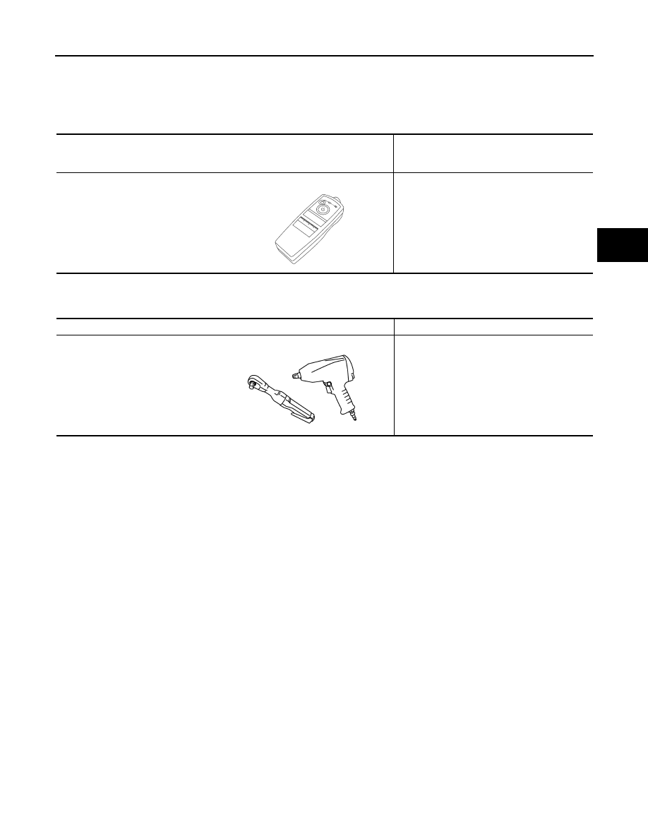
Tool number
(Kent-Moore No.)
Tool name
Description
(J-45295)
Transmitter activation tool
ID registration
SEIA0462E
Tool name
Description
Power tool
Loosen bolts and nuts
PBIC0190E

WT-6
< SERVICE INFORMATION >
NOISE, VIBRATION AND HARSHNESS (NVH) TROUBLESHOOTING
NOISE, VIBRATION AND HARSHNESS (NVH) TROUBLESHOOTING
NVH Troubleshooting Chart
INFOID:0000000001327572
Use the chart below to help you find the cause of the symptom. If necessary, repair or replace these parts.
×
: Applicable
Reference
,
,
—
—
NVH in PR section
NVH in RFD section
NVH in F
AX and FS
U
section
NVH in RAX and RSU section
Re
fe
r
to
TIRE in thi
s
ch
art.
Refe
r to
ROAD WHEE
L i
n
t
h
is cha
rt.
NVH in F
AX, RA
X section
NVH in BR section
N
V
H i
n
PS se
ctio
n
Possible cause and SUSPECTED PARTS
Im
p
rop
er i
n
s
ta
lla
tio
n
,
lo
os
en
es
s
Out-of
-round
Un
ba
la
nc
e
In
correct tire
pressure
Un
ev
en
ti
re we
ar
Def
o
rm
at
io
n
or da
ma
ge
No
n-u
n
if
orm
ity
In
co
rrec
t ti
re
si
ze
PR
OP
EL
LE
R
S
H
A
F
T
DIFFERENTIAL
F
R
ONT
AXLE AND FRONT S
U
SPENSION
REA
R
AXLE AND REAR S
U
SPENSION
TI
RE
ROAD W
H
EEL
DRIV
E SHAFT
BR
AK
E
S
T
EERING
Symptom
TIRE
Noise
×
×
×
×
×
×
×
×
×
×
×
×
×
×
×
Shake
×
×
×
×
×
×
×
×
×
×
×
×
×
×
Vibration
×
×
×
×
×
×
×
Shimmy
×
×
×
×
×
×
×
×
×
×
×
×
×
Judder
×
×
×
×
×
×
×
×
×
×
×
×
Poor quality ride
or handling
×
×
×
×
×
×
×
×
×
×
ROAD WHEEL
Noise
×
×
×
×
×
×
×
×
×
×
×
×
Shake
×
×
×
×
×
×
×
×
×
×
×
Shimmy, Judder
×
×
×
×
×
×
×
×
×
Poor quality ride
or handling
×
×
×
×
×
×
×
ROAD WHEEL
WT-7
< SERVICE INFORMATION >
C
D
F
G
H
I
J
K
L
M
A
B
WT
N
O
P
ROAD WHEEL
Inspection
INFOID:0000000001327573
ALUMINUM WHEEL
1.
Check tires for wear and improper inflation.
2.
Check wheels for deformation, cracks and other damage. If deformed, remove wheel and check wheel
runout.
a.
Remove tire from aluminum wheel and mount on a tire balance machine.
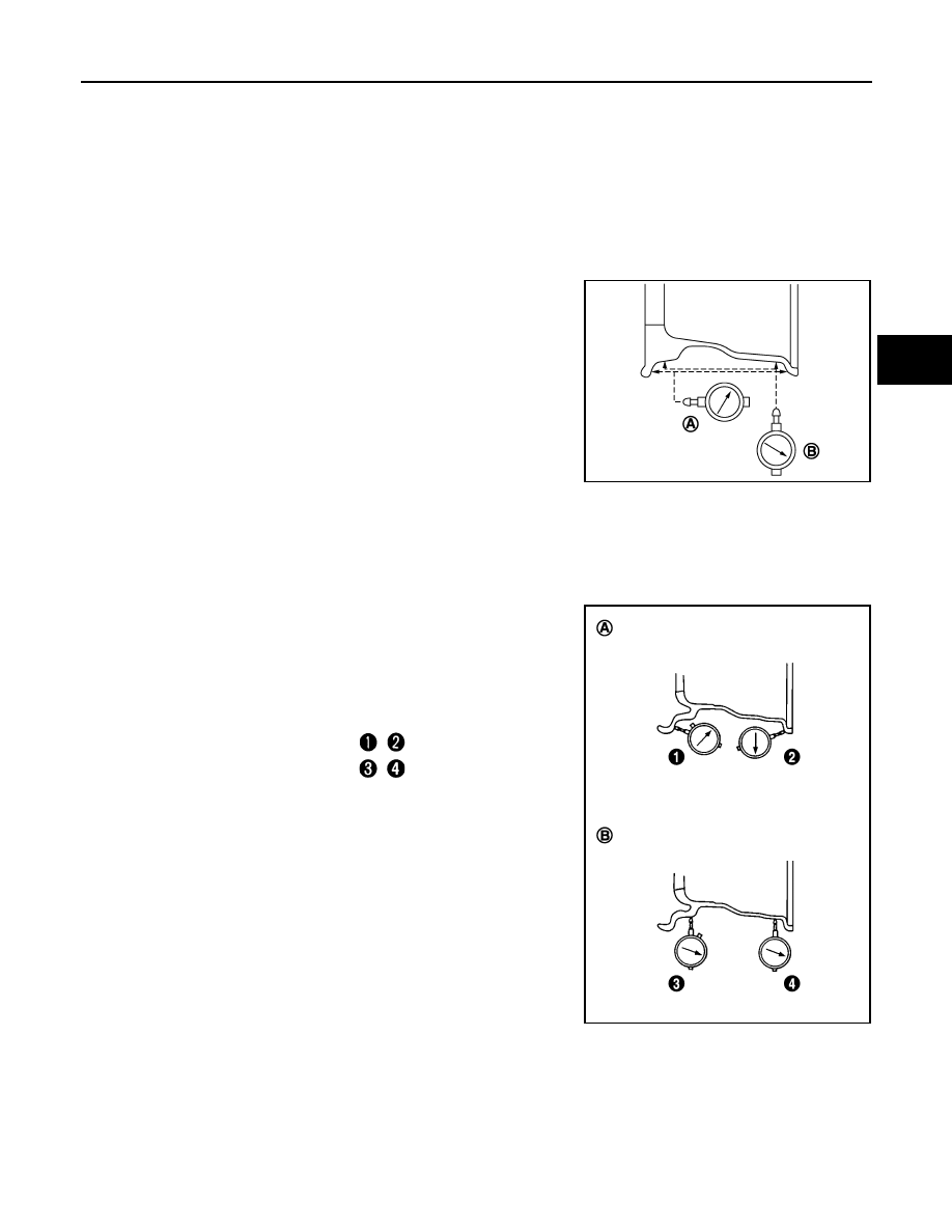
b.
Set dial indicator as shown in the illustration.
c.
If the total runout value exceeds the limit, replace aluminum
wheel.
STEEL WHEEL (FOR EMERGENCY USE)
1.
Check tires for wear and improper inflation.
2.
Check wheels for deformation, cracks and other damage. If deformed, remove wheel and check wheel
runout.
a.
Remove tire from steel wheel and mount wheel on a tire balance machine.
b.
Set two dial indicators as shown in the illustration.
c.
Set each dial indicator to “0”.
d.
Rotate wheel and check dial indicators at several points around
the circumference of the wheel.
e.
Calculate runout at each point as shown below.
f.
Select maximum positive runout value and the maximum nega-
tive value. Add the two values to determine total runout.
CAUTION:
In case a positive or negative value is not available, use the
maximum value (negative or positive) for total runout.
g.
If the total runout value exceeds the limit, replace steel wheel.
Lateral runout limit (A)
: 0.3 mm (0.012 in)
Radial runout limit (B)
: 0.3 mm (0.012 in)
SEIA0737E
Lateral runout limit (A)
: (
+
)/2
Vertical runout limit (B)
: (
+
)/2
Lateral runout limit (A)
: 1.5 mm (0.059 in)
Vertical runout limit (B)
: 1.5 mm (0.059 in)
SEIA0738E
WT-8
< SERVICE INFORMATION >
ROAD WHEEL TIRE ASSEMBLY
ROAD WHEEL TIRE ASSEMBLY
Balancing Wheels (Bonding Weight Type)
INFOID:0000000001327574
REMOVAL
Using releasing agent, remove double-faced adhesive tape from the road wheel.
CAUTION:
• Be careful not to scratch the road wheel during removal.
• After removing double-faced adhesive tape, wipe clean traces of releasing agent from the road
wheel.
WHEEL BALANCE ADJUSTMENT
• If a tire balance machine has adhesion balance weight mode settings and drive-in weight mode setting,
select and adjust a drive-in weight mode suitable for road wheels.
1.
Set road wheel on tire balance machine using the center hole as a guide. Start the tire balance machine.
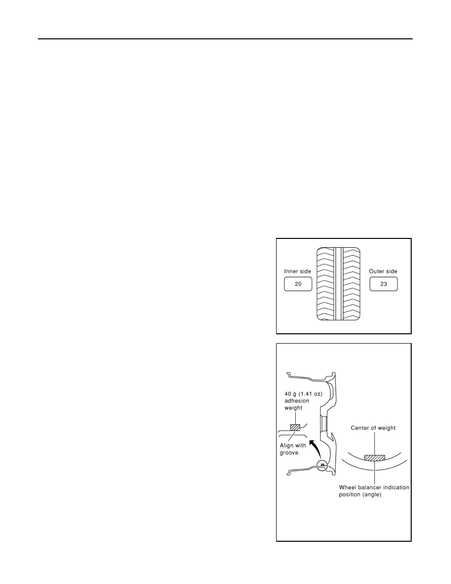
2.
When inner and outer unbalance values are shown on the tire balance machine indicator, multiply outer
unbalance value by 5/3 to determine balance weight that should be used. Select the outer balance weight
with a value closest to the calculated value above and install it to the designated outer position of, or at the
designated angle in relation to the road wheel.
CAUTION:
• Do not install the inner balance weight before installing the outer balance weight.
• Before installing the balance weight, be sure to clean the mating surface of the road wheel.
a.
Indicated unbalance value
×
5/3 = balance weight to be installed
Calculation example:
23 g (0.81 oz)
×
5/3 = 38.33 g (1.35 oz)
⇒
37.5 g (1.32 oz) bal-
ance weight (closer to calculated balance weight value)
NOTE:
Note that balance weight value must be closer to the calculated
balance weight value.
Example:
36.2
⇒
35 g (1.23 oz)
36.3
⇒
37.5 g (1.32 oz)
b.
Install balance weight in the position shown in the figure.
c.
When installing balance weight to road wheels, set it into the
grooved area on the inner wall of the road wheel as shown in the
figure so that the balance weight center is aligned with the tire
balance machine indication position (angle).
CAUTION:
• Always use genuine NISSAN adhesion balance weights.
• Balance weights are non-reusable; always replace with
new ones.
• Do not install more than three sheets of balance weight.
SMA054D
SEIA0271E
Нет комментариевНе стесняйтесь поделиться с нами вашим ценным мнением.
Текст