Infiniti FX35 / FX45. Manual — part 393
DTC P0420, P0430 THREE WAY CATALYST FUNCTION
EC-333
< SERVICE INFORMATION >
[VQ35DE]
C
D
E
F
G
H
I
J
K
L
M
A
EC
N
P
O
Overall Function Check
INFOID:0000000001326159
Use this procedure to check the overall function of the three way catalyst 1. During this check, a 1st trip DTC
might not be confirmed.
WITH GST
1.
Start engine and warm it up to the normal operating temperature.
2.
Turn ignition switch OFF and wait at least 10 seconds.
3.
Start engine and keep the engine speed between 3,500 and 4,000 rpm for at least 1 minute under no load.
4.
Let engine idle for 1 minute.
5.
Open engine hood.
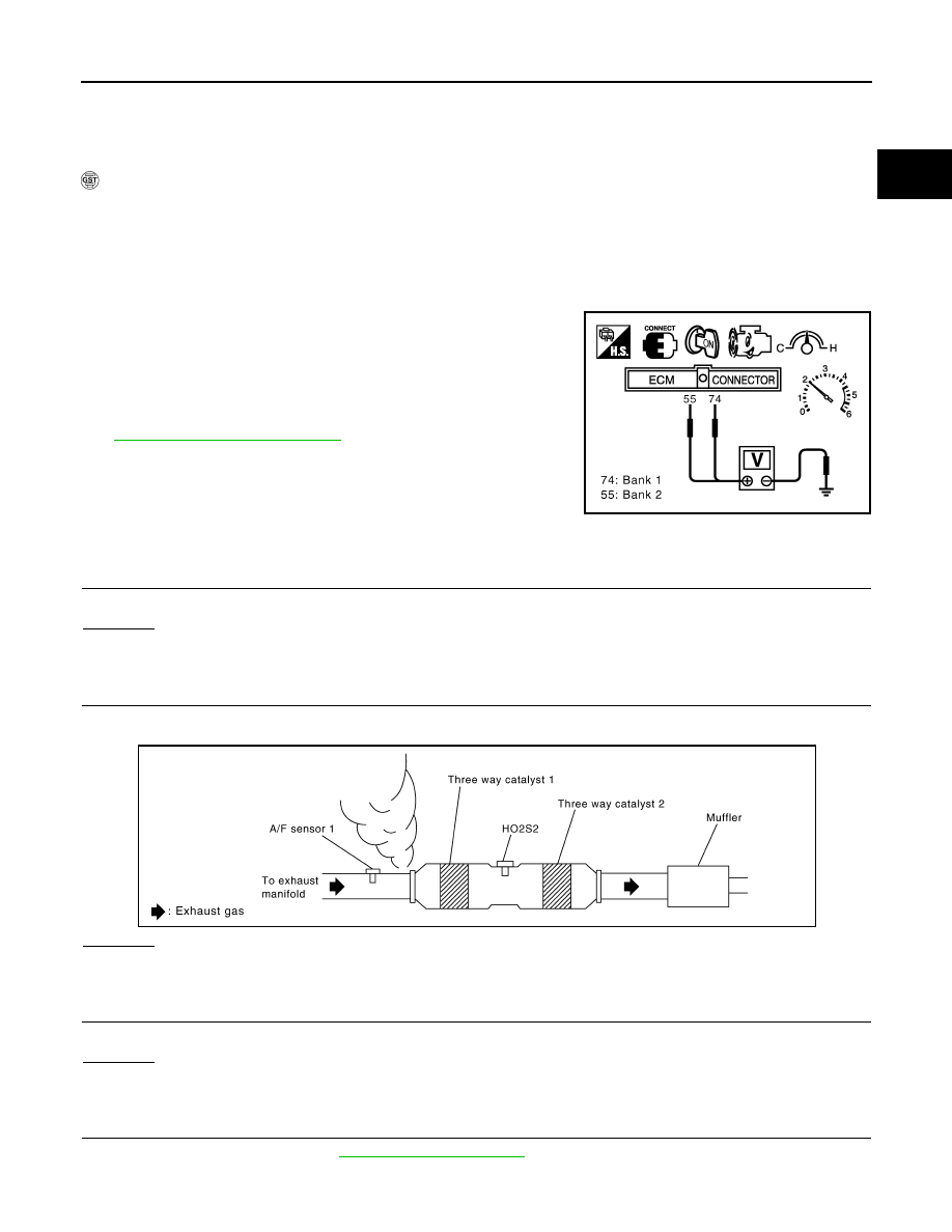
6.
Set voltmeter probes between ECM terminals 74 [HO2S2 (bank
1) signal], 55 [HO2S2 (bank 2) signal] and ground.
7.
Keep engine speed at 2,500 rpm constant under no load.
8.
Make sure that the voltage does not vary for more than 5 sec-
onds.
If the voltage fluctuation cycle takes less than 5 seconds, go to
• 1 cycle: 0.6 - 1.0
→
0 - 0.3
→
0.6 - 1.0
Diagnosis Procedure
INFOID:0000000001326160
1.
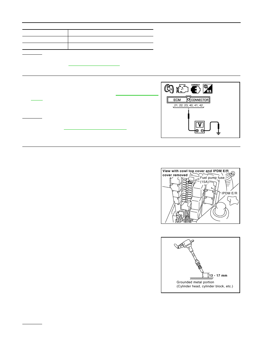
CHECK EXHAUST SYSTEM
Visually check exhaust tubes and muffler for dent.
OK or NG
OK
>> GO TO 2.
NG
>> Repair or replace.
2.
CHECK EXHAUST GAS LEAK
1.
Start engine and run it at idle.
2.
Listen for an exhaust gas leak before the three way catalyst 1.
OK or NG
OK
>> GO TO 3.
NG
>> Repair or replace.
3.
CHECK INTAKE AIR LEAK
Listen for an intake air leak after the mass air flow sensor.
OK or NG
OK
>> GO TO 4.
NG
>> Repair or replace.
4.
CHECK IGNITION TIMING
Check the following items. Refer to
PBIB1108E
PBIB1922E
EC-334
< SERVICE INFORMATION >
[VQ35DE]
DTC P0420, P0430 THREE WAY CATALYST FUNCTION
OK or NG
OK
>> GO TO 5.
NG
>> Follow the
5.
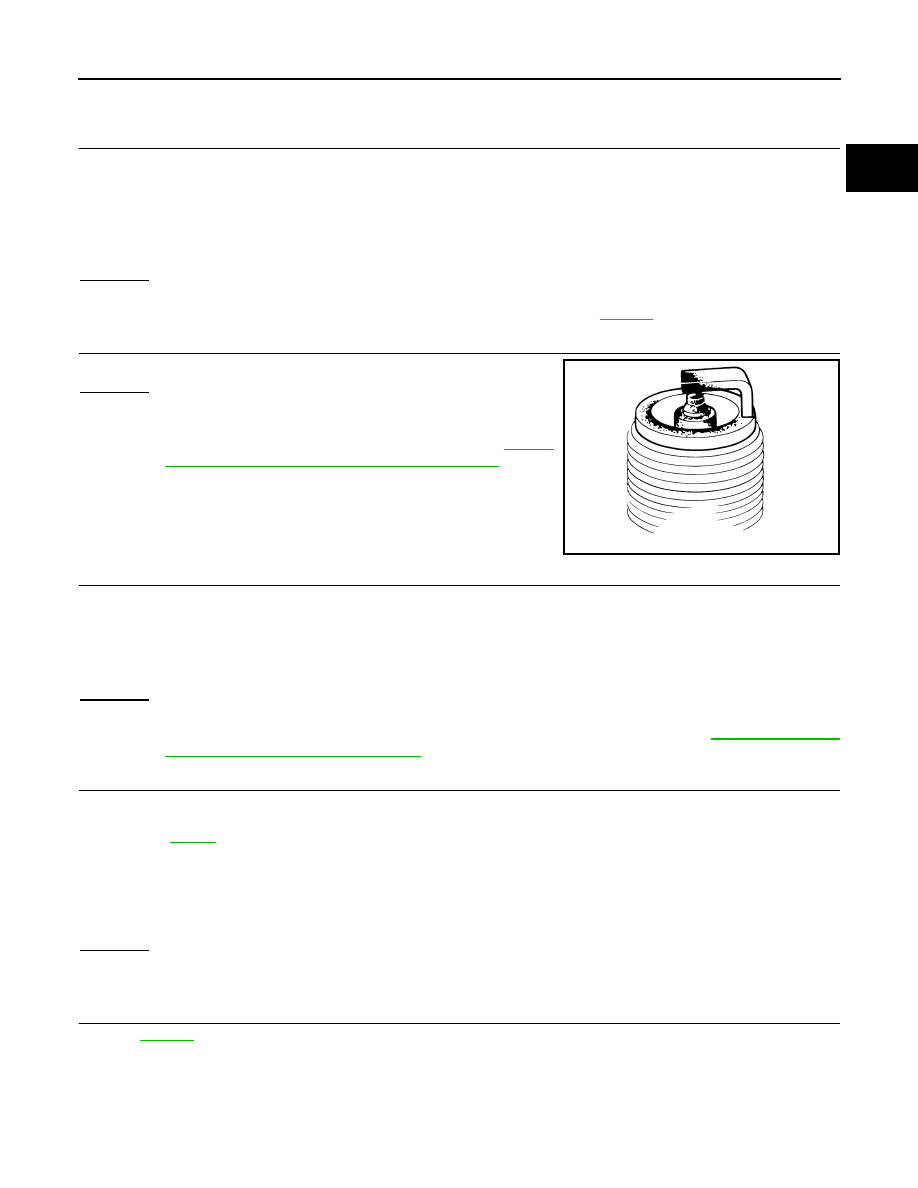
CHECK FUEL INJECTOR
1.
Stop engine and then turn ignition switch ON.
2.
Check voltage between ECM terminals 21, 22, 23, 40, 41, 42
and ground with CONSULT-III or tester.
Refer to Wiring Diagram for fuel injector,
.
OK or NG
OK
>> GO TO 6.
NG
>> Perform
.
6.
CHECK FUNCTION OF IGNITION COIL-I
CAUTION:
Do the following procedure in the place where ventilation is good without the combustible.
1.
Turn ignition switch OFF.
2.
Reconnect ECM harness connector disconnected.
3.
Remove fuel pump fuse in IPDM E/R to release fuel pressure.
NOTE:
Do not use CONSULT-III to release fuel pressure, or fuel pres-
sure applies again during the following procedure.
4.
Start engine.
5.
After engine stalls, crank it two or three times to release all fuel
pressure.
6.
Turn ignition switch OFF.
7.
Remove all ignition coil harness connectors to avoid the electri-
cal discharge from the ignition coils.
8.
Remove ignition coil and spark plug of the cylinder to be
checked.
9.
Crank engine for 5 seconds or more to remove combustion gas in the cylinder.
10. Connect spark plug and harness connector to ignition coil.
11. Fix ignition coil using a rope etc. with gap of 13 - 17 mm
between the edge of the spark plug and grounded metal portion
as shown in the figure.
12. Crank engine for about 3 seconds, and check whether spark is
generated between the spark plug and the grounded metal por-
tion.
CAUTION:
• Do not approach to the spark plug and the ignition coil
within 50cm. Be careful not to get an electrical shock
while checking, because the electrical discharge voltage
becomes 20kV or more.
• It might cause to damage the ignition coil if the gap of more than 17 mm is taken.
NOTE:
When the gap is less than 13 mm, the spark might be generated even if the coil is malfunctioning.
OK or NG
Items
Specifications
Target idle speed
650
±
50 rpm (in P or N position)
Ignition timing
15
±
5
°
BTDC (in P or N position)
Voltage: Battery voltage
PBIB2250E
Spark should be generated.
PBIB1603E
PBIB2325E
DTC P0420, P0430 THREE WAY CATALYST FUNCTION
EC-335
< SERVICE INFORMATION >
[VQ35DE]
C
D
E
F
G
H
I
J
K
L
M
A
EC
N
P
O
OK
>> GO TO 10.
NG
>> GO TO 7.
7.
CHECK FUNCTION OF IGNITION COIL-II
1.
Turn ignition switch OFF.
2.
Disconnect spark plug and connect a known-good spark plug.
3.
Crank engine for about 3 seconds, and recheck whether spark is generated between the spark plug and
the grounded metal portion.
OK or NG
OK
>> GO TO 8.
NG
>> Check ignition coil, power transistor and their circuits. Refer to
8.
CHECK SPARK PLUG
Check the spark plugs and check for fouling, etc.
OK or NG
OK
>> GO TO 9.
NG
>> Repair or replace spark plug (s) with standard type one
(s). For spark plug type ignition coil. Refer to
"Changing Spark Plugs (Platinum-Tipped Type)"
9.
CHECK FUNCTION OF IGNITION COIL-III
1.
Reconnect the initial spark plugs.
2.
Crank engine for about 3 seconds, and recheck whether spark is generated between the spark plug and
the grounded portion.
OK or NG
OK
>> INSPECTION END
NG
>> Replace spark plug(s) with standard type one(s). For spark plug type, refer to
Spark Plugs (Platinum-Tipped Type)"
.
10.
CHECK FUEL INJECTOR
1.
Turn ignition switch OFF.
2.
Remove fuel injector assembly.
Refer to
.
Keep fuel hose and all fuel injectors connected to fuel injector gallery.
3.
Disconnect all ignition coil harness connectors.
4.
Reconnect all fuel injector harness connectors disconnected.
5.
Turn ignition switch ON.
Make sure fuel does not drip from fuel injector.
OK or NG
OK (Does not drip.)>>GO TO 11.
NG (Drips.)>>Replace the fuel injector(s) from which fuel is dripping.
11.
CHECK INTERMITTENT INCIDENT
Trouble is fixed.>>INSPECTION END
Trouble is not fixed.>>Replace three way catalyst assembly.
Spark should be generated.
SEF156I
Spark should be generated.
EC-336
< SERVICE INFORMATION >
[VQ35DE]
DTC P0441 EVAP CONTROL SYSTEM
DTC P0441 EVAP CONTROL SYSTEM
System Description
INFOID:0000000001326161
NOTE:
If DTC P0441 is displayed with other DTC such as P2122, P2123, P2127, P2128 or P2138, first perform
trouble diagnosis for other DTC.
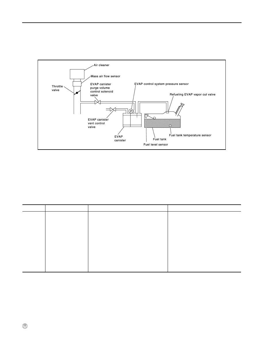
In this evaporative emission (EVAP) control system, purge flow occurs during non-closed throttle conditions.
Purge volume is related to air intake volume. Under normal purge conditions (non-closed throttle), the EVAP
canister purge volume control solenoid valve is open to admit purge flow. Purge flow exposes the EVAP con-
trol system pressure sensor to intake manifold vacuum.
On Board Diagnosis Logic
INFOID:0000000001326162
Under normal conditions (non-closed throttle), sensor output voltage indicates if pressure drop and purge flow
are adequate. If not, a malfunction is determined.
DTC Confirmation Procedure
INFOID:0000000001326163
CAUTION:
Always drive vehicle at a safe speed.
NOTE:
If DTC Confirmation Procedure has been previously conducted, always turn ignition switch OFF and wait at
least 10 seconds before conducting the next test.
TESTING CONDITION:
Always perform test at a temperature of 5
°
C (41
°
F) or more.
WITH CONSULT-III
PBIB1026E
DTC No.
Trouble diagnosis name
DTC detecting condition
Possible cause
P0441
0441
EVAP control system in-
correct purge flow
EVAP control system does not operate proper-
ly, EVAP control system has a leak between in-
take manifold and EVAP control system
pressure sensor.
• EVAP canister purge volume control so-
lenoid valve stuck closed
• EVAP control system pressure sensor
and the circuit
• Loose, disconnected or improper con-
nection of rubber tube
• Blocked rubber tube
• Cracked EVAP canister
• EVAP canister purge volume control so-
lenoid valve circuit
• Accelerator pedal position sensor
• Blocked purge port
• EVAP canister vent control valve
Нет комментариевНе стесняйтесь поделиться с нами вашим ценным мнением.
Текст