Infiniti FX35 / FX45. Manual — part 133
ATC-128
< SERVICE INFORMATION >
REFRIGERANT LINES
5.
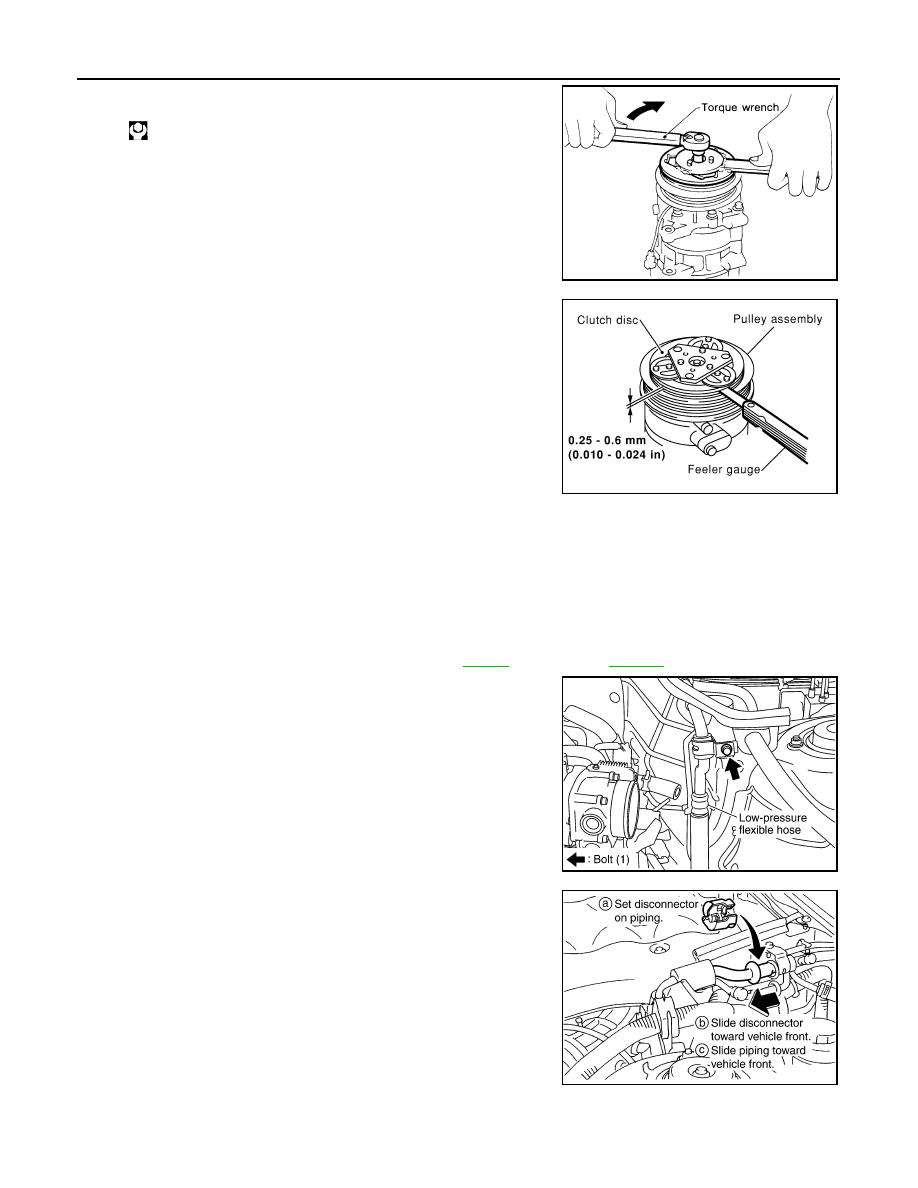
Using holder to prevent clutch disc rotation.
After tightening bolt, make sure pulley rotates smoothly.
6.
Check clearance around entire periphery of clutch disc.
If specified clearance is not obtained, replace adjusting spacer
and readjust.
Break-in Operation
When replacing compressor clutch assembly, always carry out break-in operation. This is done by engaging
and disengaging clutch about thirty-times. Break-in operation raises the level of transmitted torque.
Removal and Installation of Low-Pressure Flexible Hose
INFOID:0000000001328221
REMOVAL
1.
Use a refrigerant collecting equipment (for HFC-134a) to discharge the refrigerant.
2.
Remove the air cleaner case and air duct. Refer to
(VQ35DE) or
3.
Remove low-pressure flexible hose bracket mounting bolt.
4.
Disconnect one-touch joint between low-pressure flexible hose
and low-pressure pipe 1.
a.
Set a disconnector (SST: 9253089916) on A/C piping.
b.
Slide a disconnector toward vehicle front until it clicks.
c.
Slide A/C piping toward vehicle front and disconnect it.
CAUTION:
Cap or wrap the joint of low-pressure flexible hose and low-
pressure pipe 1 with suitable material such as vinyl tape to
avoid the entry of air.
: 14 N·m (1.4 kg-m, 10 ft-lb)
RHA086E
Disc to pulley clear-
ance
: 0.25 - 0.6 mm (0.010 - 0.024 in)
RJIA0965E
RJIA2062E
RJIA2069E
REFRIGERANT LINES
ATC-129
< SERVICE INFORMATION >
C
D
E
F
G
H
I
K
L
M
A
B
ATC
N
O
P
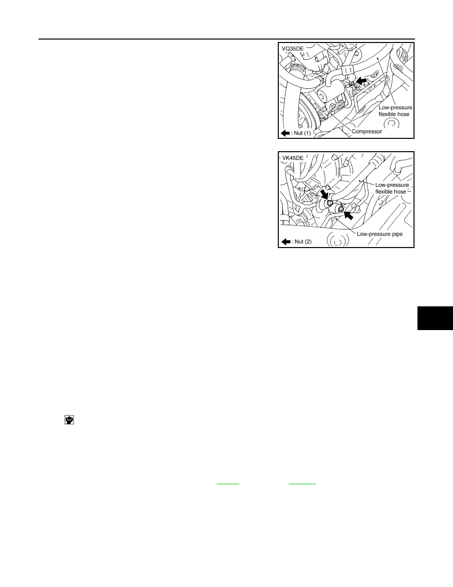
5.
Remove mounting nut from low-pressure flexible hose.
6.
Remove mounting nut, and then remove low-pressure pipe
(VK45DE).
CAUTION:
Cap or wrap the joint of compressor and low-pressure flexi-
ble hose with suitable material such as vinyl tape to avoid
the entry of air.
7.
Remove low-pressure flexible hose.
CAUTION:
Cap or wrap the joint of compressor and low-pressure pipe 1 with suitable material such as vinyl
tape to avoid the entry of air.
INSTALLATION
Installation is basically the reverse order of removal.
CAUTION:
• Replace O-rings of low-pressure flexible hose and low-pressure pipe (VK45DE) with new ones, and
then apply compressor oil to it when installing it.
• Female-side piping connection is thin and easy to deform. Slowly insert the male-side piping
straight in axial direction.
• Insert piping securely until a click is heard.
• After piping connection is completed, pull male-side piping by hand to make sure that connection
does not come loose.
• When recharging refrigerant, check for leaks.
Removal and Installation of High-pressure Flexible Hose
INFOID:0000000001328222
REMOVAL
1.
Use a refrigerant collecting equipment (for HFC-134a) to discharge the refrigerant.
2.
Remove air cleaner case and air duct. Refer to
(VQ35DE) or
RJIA2064E
RJIA2063E
Low-pressure flexible hose bracket mounting bolt
: 5.5 N·m (0.56 kg-m, 49 in-lb)
ATC-130
< SERVICE INFORMATION >
REFRIGERANT LINES
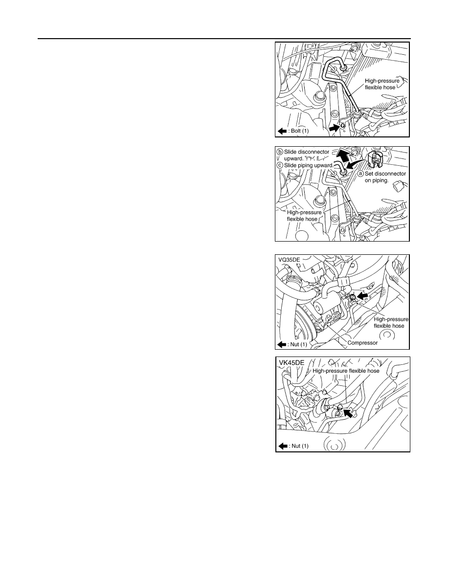
3.
Remove high-pressure flexible hose bracket mounting bolt.
4.
Disconnect one-touch joint between high-pressure flexible hose
and condenser.
a.
Set a disconnector (SST: 9253089912) on A/C piping.
b.
Slide a disconnector upward until it clicks.
c.
Slide A/C piping upward and disconnect it.
CAUTION:
Cap or wrap the joint of condenser and high-pressure flexi-
ble hose with suitable material such as vinyl tape to avoid
the entry of air.
5.
Remove mounting nut from high-pressure flexible hose (com-
pressor side), and then remove high-pressure flexible hose.
CAUTION:
Cap or wrap the joint of compressor and high-pressure flex-
ible hose with suitable material such as vinyl tape to avoid
the entry of air.
INSTALLATION
Installation is basically the reverse order of removal.
CAUTION:
• Replace O-rings of high-pressure flexible hose with new ones, and then apply compressor oil to it
when installing it.
• Female-side piping connection is thin and easy to deform. Slowly insert the male-side piping
straight in axial direction.
• Insert piping securely until a click is heard.
• After piping connection is completed, pull male-side piping by hand to make sure that connection
does not come loose.
• When recharging refrigerant, check for leaks.
RJIA2065E
RJIA2066E
SJIA0943E
RJIA2067E
REFRIGERANT LINES
ATC-131
< SERVICE INFORMATION >
C
D
E
F
G
H
I
K
L
M
A
B
ATC
N
O
P
Removal and Installation of Low-Pressure Pipe 1 (Engine Compartment)
INFOID:0000000001328223
REMOVAL
1.
Use a refrigerant collecting equipment (for HFC-134a) to discharge the refrigerant.
2.
Remove cowl top cover. Refer to
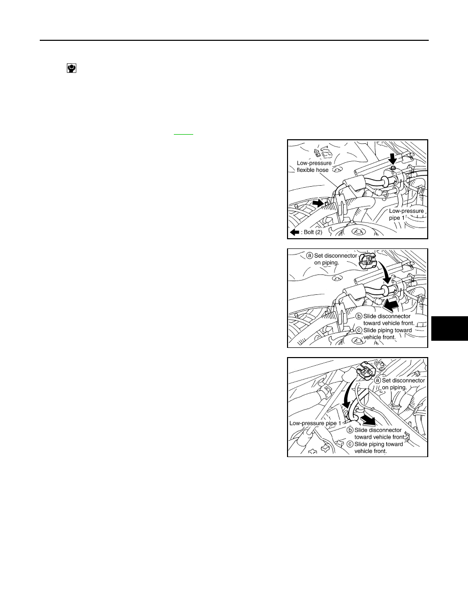
3.
Remove low-pressure pipe 1 bracket and low-pressure flexible
hose bracket mounting bolts.
4.
Disconnect one-touch joints.
a.
Set a disconnector (SST: 9253089916) on A/C piping.
b.
Slide a disconnector toward vehicle front until it clicks.
c.
Slide A/C piping toward vehicle front and disconnect it.
5.
Remove low-pressure pipe 1.
CAUTION:
Cap or wrap the joint of low-pressure pipe 1 and 2 with suit-
able material such as vinyl tape to avoid the entry of air.
INSTALLATION
Installation is basically the reverse order of removal.
CAUTION:
• Replace O-rings of low-pressure pipe 1 with new ones, and then apply compressor oil to it when
installing it.
• Female-side piping connection is thin and easy to deform. Slowly insert the male-side piping
straight in axial direction.
• Insert piping securely until a click is heard.
• After piping connection is completed, pull male-side piping by hand to make sure that connection
does not come loose.
• When recharging refrigerant, check for leaks.
High-pressure flexible hose bracket mounting bolt
: 5.5 N·m (0.56 kg-m, 49 in-lb)
RJIA2068E
RJIA2069E
RJIA2037E
Нет комментариевНе стесняйтесь поделиться с нами вашим ценным мнением.
Текст