Infiniti FX35 / FX45. Manual — part 134

ATC-132
< SERVICE INFORMATION >
REFRIGERANT LINES
Removal and Installation of High-pressure Pipe 1 and 2 (Engine Compartment)
INFOID:0000000001328224
REMOVAL
1.
Remove low-pressure pipe 1. Refer to
ATC-131, "Removal and Installation of Low-Pressure Pipe 1
.
2.
Remove high-pressure flexible hose and low-pressure flexible hose. Refer to
Installation of High-pressure Flexible Hose"
ATC-128, "Removal and Installation of Low-Pressure
3.
Remove high-pressure pipe 1 and 2 from clips.
4.
Disconnect one-touch joint between condenser and high-pres-
sure pipe 1.
a.
Set a disconnector (SST: 9253089908) on A/C piping.
b.
Slide a disconnector upward until it clicks.
c.
Slide A/C piping upward and disconnect it.
CAUTION:
Cap or wrap the joint of condenser and high-pressure pipe
1 with suitable material such as vinyl tape to avoid the entry
of air.
5.
Disconnect one-touch joint between high-pressure pipe 1 and 2.
a.
Set a disconnector (SST: 9253089908) on A/C piping.
b.
Slide a disconnector toward vehicle rear until it clicks.
c.
Slide A/C piping toward vehicle rear and disconnect it.
CAUTION:
Cap or wrap the joint of high-pressure pipe 1 and 2 with
suitable material such as vinyl tape to avoid the entry of air.
6.
Remove high-pressure pipe 1.
Low-pressure pipe 1 bracket and low-pressure flexible hose bracket mounting bolts
: 5.5 N·m (0.56 kg-m, 49 in-lb)
RJIA2070E
RJIA2071E
RJIA2072E
REFRIGERANT LINES
ATC-133
< SERVICE INFORMATION >
C
D
E
F
G
H
I
K
L
M
A
B
ATC
N
O
P
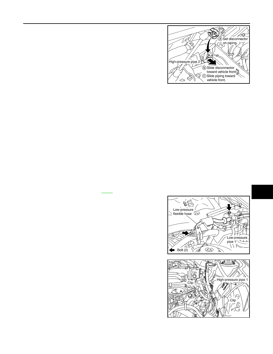
7.
Disconnect one-touch joint between high-pressure pipe 2 and 3.
a.
Set a disconnector (SST: 9253089908) on A/C piping.
b.
Slide a disconnector toward vehicle front until it clicks.
c.
Slide A/C piping toward vehicle front and disconnect it.
8.
Remove high-pressure pipe 2.
CAUTION:
Cap or wrap the joint of high-pressure pipe 2 and 3 with
suitable material such as vinyl tape to avoid the entry of air.
INSTALLATION
Installation is basically the reverse order of removal.
CAUTION:
• Replace O-rings of high-pressure pipe 1 and 2 with new ones, and then apply compressor oil to it
when installing it.
• Female-side piping connection is thin and easy to deform. Slowly insert the male-side piping
straight in axial direction.
• Insert piping securely until a click is heard.
• After piping connection is completed, pull male-side piping by hand to make sure that connection
does not come loose.
• When recharging refrigerant, check for leaks.
Removal and Installation of Low-Pressure Pipe 2 and High-pressure Pipe 3
INFOID:0000000001328225
REMOVAL
1.
Set the temperature (passenger side) at 18
°
C (60
°
F), and then disconnect the battery cable from the neg-
ative terminal.
2.
Use a refrigerant collecting equipment (for HFC-134a) to discharge the refrigerant.
3.
Remove cowl top cover. Refer to
4.
Remove low-pressure pipe 1 bracket and low-pressure flexible
hose bracket mounting bolts.
5.
Remove high-pressure pipe 1 from vehicle clips.
RJIA2073E
RJIA2068E
RJIA2070E

ATC-134
< SERVICE INFORMATION >
REFRIGERANT LINES
6.
Disconnect one-touch joints.
a.
Set a disconnector [high-pressure side (SST: 9253089908), low-
pressure side (SST: 9253089916)] on A/C piping.
b.
Slide a disconnector toward vehicle front until it clicks.
c.
Slide A/C piping toward vehicle front and disconnect it.
CAUTION:
Cap or wrap the joint of low-pressure pipe 1 and high-pres-
sure pipe 2 with suitable material such as vinyl tape to
avoid the entry of air.
7.
Remove blower unit. Refer to
.
8.
Remove mounting screws, and then remove air mix door motor
(passenger side), mode door motor and evaporator cover.
9.
Remove mounting bolt, and then remove low-pressure pipe 2
and high-pressure pipe 3.
CAUTION:
Cap or wrap the joint of expansion valve with suitable mate-
rial such as vinyl tape to avoid the entry of air.
INSTALLATION
Installation is basically the reverse order of removal.
CAUTION:
• Replace O-rings of low-pressure pipe 1, 2 and high-pressure pipe 2, 3 with new ones, and then apply
compressor oil to it when installing it.
• Female-side piping connection is thin and easy to deform. Slowly insert the male-side piping
straight in axial direction.
• Insert piping securely until a click is heard.
• After piping connection is completed, pull male-side piping by hand to make sure that connection
does not come loose.
• When recharging refrigerant, check for leaks.
Removal and Installation of Liquid Tank
INFOID:0000000001328226
REMOVAL
1.
Use a refrigerant collecting equipment (for HFC-134a) to discharge the refrigerant.
2.
Remove front grille. Refer to
.
3.
Clean liquid tank and its surrounding area, and remove dust and rust from liquid tank.
CAUTION:
RJIA2037E
RJIA0940E
RJIA2038E
Low-pressure pipe 1 bracket and low-pressure flexible hose bracket mounting bolts
: 5.5 N·m (0.56 kg-m, 49 in-lb)
REFRIGERANT LINES
ATC-135
< SERVICE INFORMATION >
C
D
E
F
G
H
I
K
L
M
A
B
ATC
N
O
P
Be sure to clean carefully.
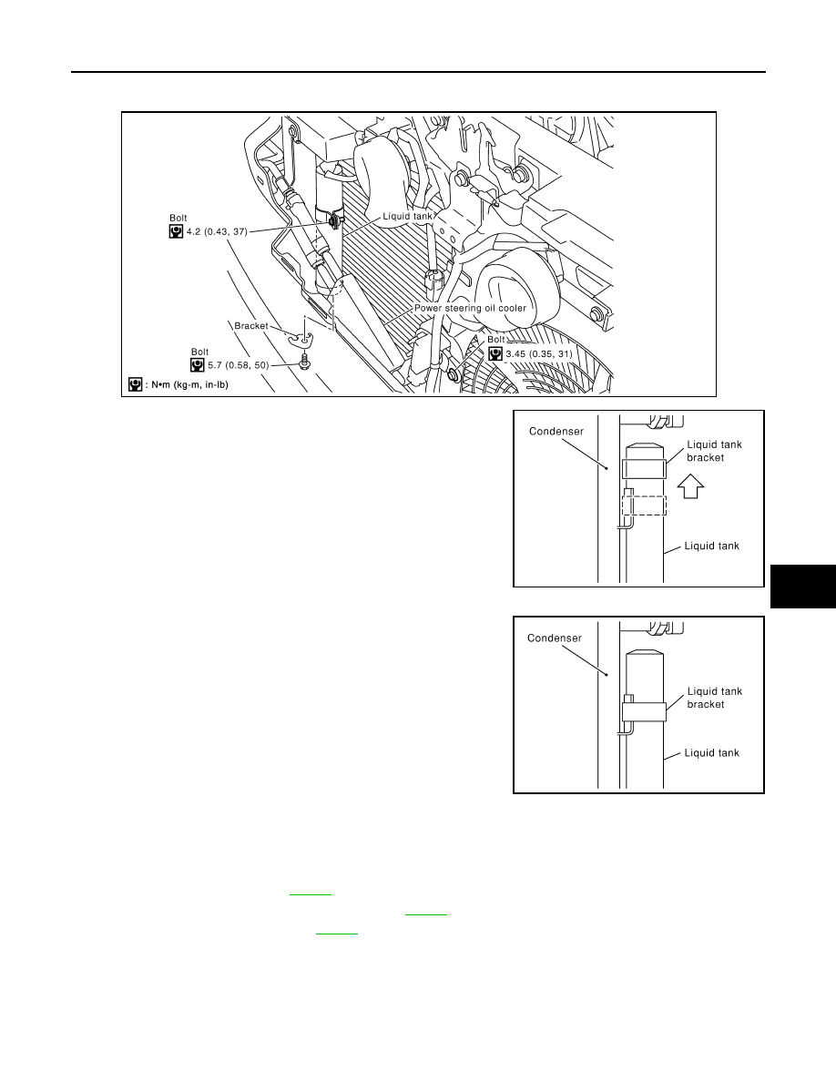
4.
Remove liquid tank and power steering oil cooler mounting bolts.
5.
Lift liquid tank bracket upward. Remove liquid tank bracket from
protruding part of condenser.
6.
Slide liquid tank upward, and then remove liquid tank.
INSTALLATION
Install liquid tank, and then install liquid tank bracket on condenser.
CAUTION:
• Make sure liquid tank bracket is securely installed at protru-
sion of condenser. (Make sure liquid tank bracket does not
move to a position below center of liquid tank.)
• Replace O-rings of condenser pipe with new ones, and then
apply compressor oil to it when installing it.
• When recharging refrigerant, check for leaks.
Removal and Installation of Condenser
INFOID:0000000001328227
REMOVAL
1.
Use a refrigerant collecting equipment (for HFC-134a) to discharge the refrigerant.
2.
Remove cooling fan. Refer to
3.
Remove radiator cooling fan assembly. Refer to
4.
Remove radiator shroud. Refer to
(VK45DE).
SJIA1644E
RJIA0672E
RJIA0673E
Нет комментариевНе стесняйтесь поделиться с нами вашим ценным мнением.
Текст