Infiniti FX35 / FX45. Manual — part 178
AV-166
< SERVICE INFORMATION >
TELEPHONE
Terminal and Reference Value for TEL Adapter Unit
INFOID:0000000001328793
Terminal
(Wire color)
Item
Signal
input/
output
Condition
Reference value
+
–
Ignition
switch
Operation
1 (W/L)
Ground
Battery power supply
Input
OFF
—
Battery voltage
2 (LG)
Ground
ACC power supply
Input
ACC
—
Battery voltage
3 (W)
Ground
Ignition signal
Input
ON
—
Battery voltage
4 (B)
Ground
Ground
—
ON
—
Approx. 0 V
6
—
Shield
—
—
—
—
7 (R)
8 (B)
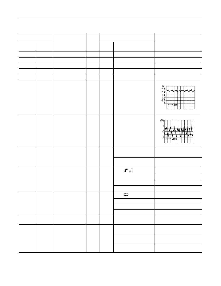
MIC. signal
Input
ON
Uttering in front of the micro-
phone while using the
hands-free phone system.
9 (P)
10 (L)
TEL voice signal
Output
ON
Receiving the party's voice
while using the hands-free
phone system.
11 (L/W)
Ground
TEL ON signal
Output
ON
While using handsfree
phone system.
Approx. 0 V
While not using handsfree
phone system.
Approx. 5 V
12 (LG)
Ground
Remote control A
Input
ON
Press
switch
Approx. 0 V
Press SEEK UP switch
Approx. 1.7 V
Press VOL UP switch
Approx. 3.3 V
Except for above
Approx. 5 V
13 (GY)
Ground
Remote control B
Input
ON
Press
switch
Approx. 0 V
Press SEEK DOWN switch
Approx. 1.7 V
Press VOL DOWN switch
Approx. 3.3 V
Except for above
Approx. 5 V
14 (SB)
Ground
Remote control
ground
—
ON
—
Approx. 0 V
15 (PU)
Ground
Indicator signal
Output
ON
Microphone indicator ON,
and lighting switch OFF
Approx. 1.3 V
Microphone indicator ON,
and lighting switch ON
Approx. 0.8 V
Microphone unit indicator
OFF
Approx. 12 V
PKIB5037J
SKIB3609E
TELEPHONE
AV-167
< SERVICE INFORMATION >
C
D
E
F
G
H
I
J
L
M
A
B
AV
N
O
P
Self-Diagnosis Function
INFOID:0000000001328794
The followings are diagnosis functions performed by TEL adapter unit.
• Performs the unit self
−
diagnosis and antenna diagnosis, and informs results with the indicator and voice
guidance.
• Informs vehicle speed pulse count from the time of key switch ON with voice guidance, and enables to check
vehicle speed signal.
• Outputs voice giving to microphone with speaker, and enables to check microphone function.
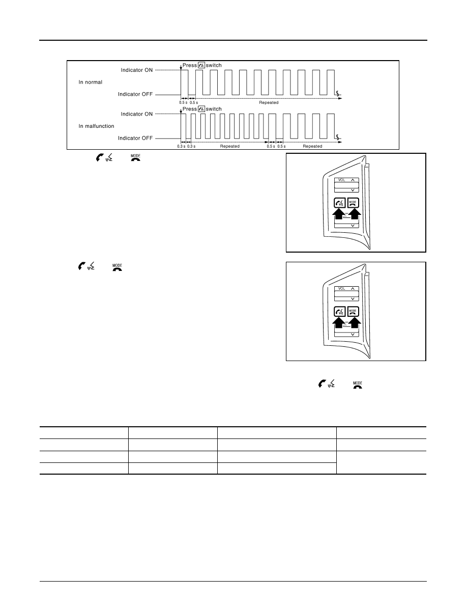
OPERATION PROCEDURE
1.
Start the engine.
2.
Press and hold
switch for 5 seconds or more.
• This allows the indicator to blink concurrently with voice guidance outputs, and determines if there is any
current error in the state of blinking.
17 (R/W)
Ground
Remote control A
Output
ON
Press
switch
Approx. 0 V
Press SEEK UP switch
Approx. 1.7 V
Press VOL UP switch
Approx. 3.3 V
Except for above
Approx. 5 V
18 (G/W)
Ground
Remote control B
Output
ON
Press
switch
Approx. 0 V
Press SEEK DOWN switch
Approx. 1.7 V
Press VOL DOWN switch
Approx. 3.3 V
Except for above
Approx. 5 V
19 (B/Y)
Ground
Remote control
ground
—
ON
—
Approx. 0 V
22 (B)
Ground
Ground
—
ON
—
Approx. 0 V
23 (B)
Ground
Ground
—
ON
—
Approx. 0 V
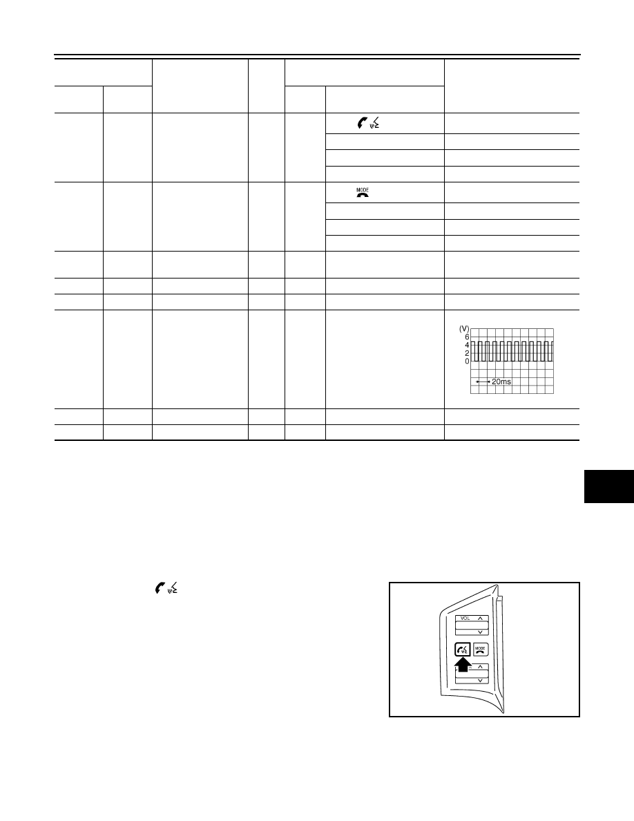
28 (G)
Ground
Vehicle
speed signal
(8-pulse)
Input
ON
When vehicle speed is ap-
prox. 40 km/h (25 MPH)
29 (W)
Ground
MIC. VCC
Output
ON
—
Approx. 5 V
41 —
TEL
signal
—
—
—
—
Terminal
(Wire color)
Item
Signal
input/
output
Condition
Reference value
+
–
Ignition
switch
Operation
SKIA6649J
SKIB7570E
AV-168
< SERVICE INFORMATION >
TELEPHONE
• When the indicator does not blink, check the microphone power supply circuit, and then repair malfunc-
tioning part.
3.
Press both
and
switch simultaneously while voice guid-
ance outputs.
4.
Press
and
switch simultaneously while beep sound out-
puts.
CAUTION:
Turn ignition switch OFF and return to Step 1 again if beep
sound does not output. Replace TEL adapter unit if beep
sound still does not output.
5.
Perform the followings.
• Check how many times indicator flashes within 5 seconds after pressing
and
switch.
• Inform the malfunction and vehicle speed pulse from the time of ignition switch ON with voice.
NOTE:
Vehicle speed pulse is reset to 0 when turning ignition switch OFF.
6.
Beep sounds (while 1 second) outputs 3 seconds after voice guidance of microphone check.
7.
Voice giving to microphone outputs from speaker. Microphone function can be checked.
8.
Diagnosis mode exits after a beep sounds.
Basic Inspection of Hands-Free Phone
INFOID:0000000001328795
Check the parts or circuit listed below when the hands-free phone system is inoperative at all or a communica-
tion error exists between TEL and TEL adopter unit.
• TEL
• TEL adapter unit power supply circuit
1.
CHECK INDICATOR OPERATION
SKIB7572E
SKIB7571E
SKIB7571E
Number of indicator flashes
Voice guidance
Malfunction
Possible solution
1
Internal failure
TEL adapter unit is malfunctioning
Replace TEL adapter unit
2
Bluetooth antenna open
TEL antenna feeder is open
Replace TEL antenna
3
Bluetooth antenna shorted
TEL antenna feeder is short
TELEPHONE
AV-169
< SERVICE INFORMATION >
C
D
E
F
G
H
I
J
L
M
A
B
AV
N
O
P
1.
Turn ignition switch ACC.
2.
Check the indicator is blinking.
OK or NG
OK
>> GO TO 2
NG
>> Check indicator circuit and MIC. circuit.
2.
CHECK AUDIO STEERING WHEEL SWITCH OPERATION
1.
Press the
switch.
2.
Check the indicator is blinking.
OK or NG
OK
>> INSPECTION END
NG
>> Check audio steering wheel switch circuit.
Audio Steering Wheel Switch Does Not Operate
INFOID:0000000001328796
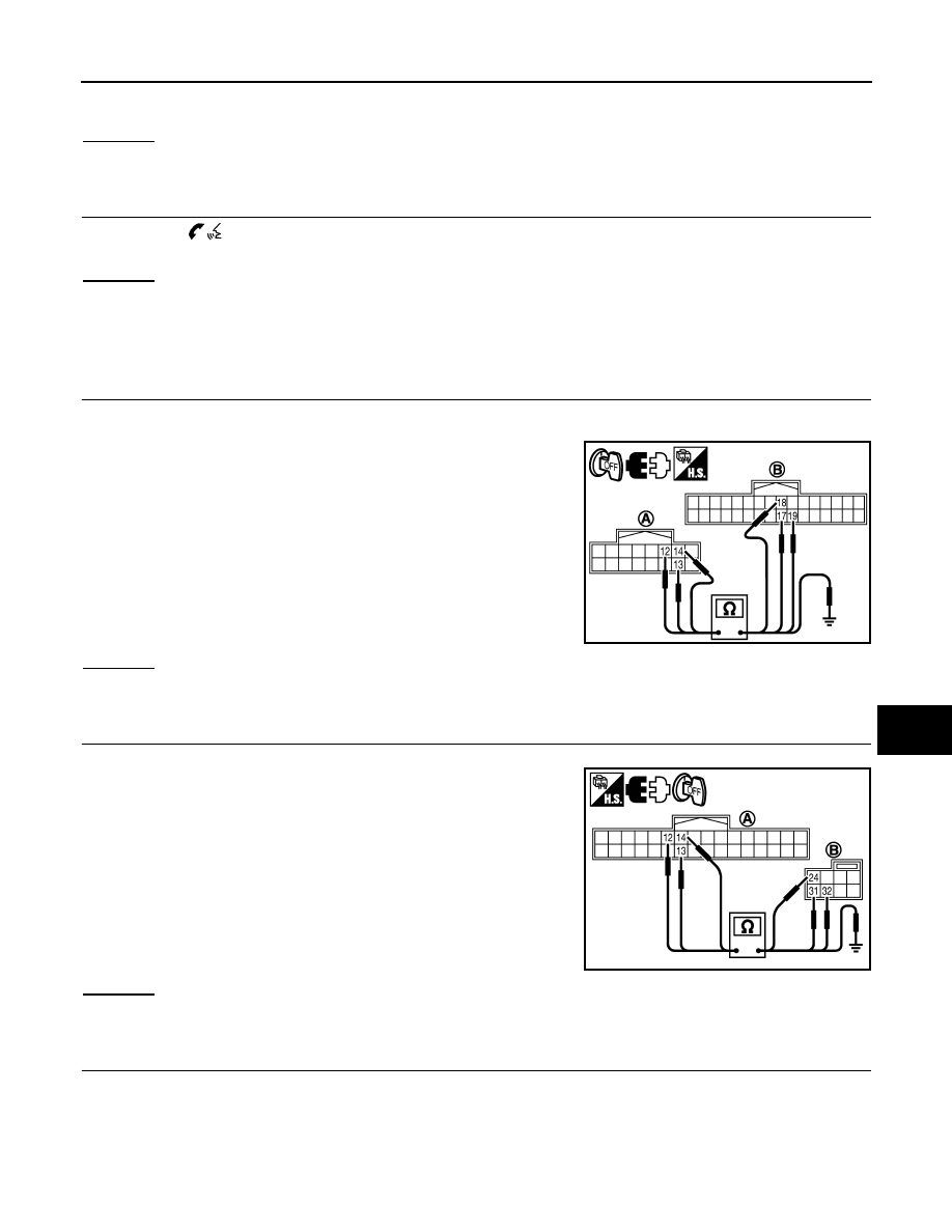
1.
CHECK HARNESS
1.
Turn ignition switch OFF.
2.
Disconnect A/C and AV switch and TEL adapter unit connectors.
3.
Check continuity between A/C and AV switch harness connector
(A) M64 terminals 12, 13, 14 and teladapter unit harness con-
nector (B) M102 terminals 17, 18, 19.
4.
Check continuity between A/C and AV switch and ground.
OK or NG
OK
>> GO TO 2.
NG
>> Repair harness or connector.
2.
CHECK HARNESS
1.
Disconnect spiral cable connector.
2.
Check continuity between TEL adapter unit harness connector
(A) M102 terminals 12, 13, 14 and spiral cable harness connec-
tor (B) M15 terminals 24, 32, 31.
3.
Check continuity between TEL adapter unit and ground.
OK or NG
OK
>> GO TO 3.
NG
>> Repair harness or connector.
3.
CHECK SPIRAL CABLE
1.
Disconnect spiral cable connector (Audio steering wheel switch harness side).
12 – 17
: Continuity should exist.
13 – 18
: Continuity should exist.
14 – 19
: Continuity should exist.
12, 13, 14 – ground
: Continuity should not exist.
PKIC9369E
12 – 24
: Continuity should exist.
13 – 32
: Continuity should exist.
14 – 31
: Continuity should exist.
12, 13, 14 – ground
: Continuity should not exist.
SKIB8681E
Нет комментариевНе стесняйтесь поделиться с нами вашим ценным мнением.
Текст