Infiniti FX35 / FX45. Manual — part 179
AV-170
< SERVICE INFORMATION >
TELEPHONE
2.
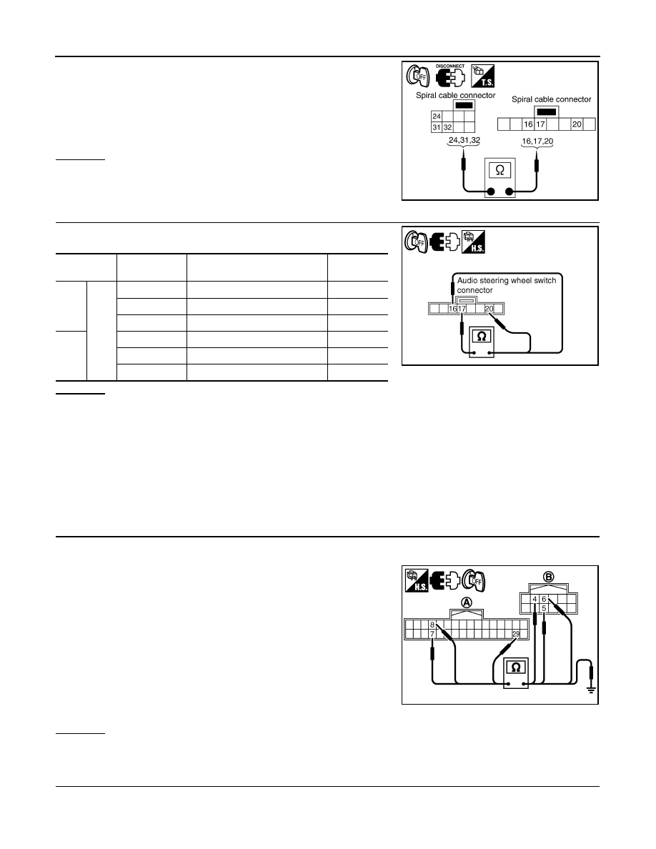
Check continuity between spiral cable connector M15 terminals
24, 31, 32 and spiral cable connector M203 terminals 20, 17, 16.
OK or NG
OK
>> GO TO 4.
NG
>> Replace spiral cable.
4.
CHECK AUDIO STEERING WHEEL SWITCH RESISTANCE
Check resistance audio steering wheel switch terminals.
OK or NG
OK
>> INSPECTION END
NG
>> Replace audio steering wheel switch.
Voice Activated Control Function Does Not Operate
INFOID:0000000001328797
NOTE:
Even under the normal condition, TEL voice guidance may not occur when pressing audio steering wheel
switch.
TEL VOICE GUIDANCE IS HEARD WHEN PRESSING AUDIO STEERING WHEEL SWITCH
1.
CHECK HARNESS BETWEEN TEL ADAPTER UNIT AND MICROPHONE UNIT
1.
Turn ignition switch OFF.
2.
Disconnect TEL adapter unit and microphone unit connectors.
3.
Check continuity between TEL adapter unit harness connector
(A) M102 terminals 7, 8, 29 and microphone unit harness con-
nector (B) R59 terminals 5, 6, 4.
4.
Check continuity between TEL adapter unit harness connector
(A) M102 terminals 7, 8, 29 and ground.
OK or NG
OK
>> GO TO 2.
NG
>> Repair harness or connector.
2.
CHECK MIC. POWER SUPPLY
1.
Connect TEL adapter unit and microphone unit connectors.
2.
Turn ignition switch ON.
24 – 20
: Continuity should exist.
31 – 17
: Continuity should exist.
32 – 16
: Continuity should exist.
SKIA5874E
Terminal
Signal name
Condition
Resistance
(
Ω
)
16
17
Mode
Depress mode switch.
Approx. 0
Seek down
Depress (station) down switch.
Approx. 165
Volume (down)
Depress volume down switch.
Approx. 652
20
PTT
Depress PTT switch.
Approx. 0
Seek up
Depress (station) up switch.
Approx. 165
Volume (up)
Depress volume up switch.
Approx. 652
SKIA5010E
7 – 5
: Continuity should exist.
8 – 6
: Continuity should exist.
29 – 4
: Continuity should exist.
7, 8, 29 – Ground
: Continuity should not exist.
SKIB7348E
TELEPHONE
AV-171
< SERVICE INFORMATION >
C
D
E
F
G
H
I
J
L
M
A
B
AV
N
O
P
3.
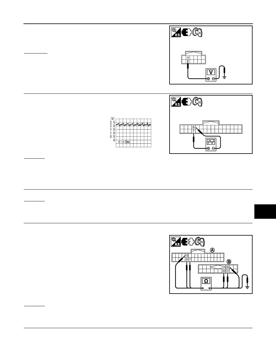
Check voltage between microphone unit harness connector R59
terminal 4 and ground.
YES or NO
YES
>> GO TO 3.
NO
>> Replace TEL adapter unit.
3.
CHECK MIC. SIGNAL
1.
Check signal between TEL adapter unit harness connector
M102 terminal 7 and 8.
OK or NG
OK
>> Replace TEL adapter unit.
NG
>> Replace microphone unit.
TEL VOICE GUIDANCE IS NOT HEARD WHEN PRESSING AUDIO STEERING WHEEL SWITCH
1.
CHECK AUDIO STEERING WHEEL SWITCH CIRCUIT
Refer to "Voice Activated Control Function Does Not Operate".
OK or NG
OK
>> GO TO 2.
NG
>> Replace applicable parts.
2.
CHECK TEL VOICE SIGNAL CIRCUIT
1.
Turn ignition switch OFF.
2.
Disconnect TEL adapter unit and audio unit connectors.
3.
Check continuity between TEL adapter unit harness connector
(A) M102 terminals 9, 10, 11 and audio unit harness connector
(B) M60 terminals 31, 30, 32.
4.
Check continuity between TEL adapter unit harness connector
(A) M102 terminals 9, 10, 11and ground.
OK or NG
OK
>> GO TO 3.
NG
>> Repair harness or connector.
3.
CHECK MUTE SIGNAL
1.
Connect TEL adapter unit connector and audio unit connectors.
2.
Turn ignition switch ON.
4 – Ground
: Approx. 5 V
SKIB7349E
7 – 8:
When giving a voice
SKIB7350E
PKIB5037J
9 – 31
: Continuity should exist.
10 – 30
: Continuity should exist.
11 – 32
: Continuity should exist.
9, 10, 11 – Ground
: Continuity should not exist.
PKIC9370E
AV-172
< SERVICE INFORMATION >
TELEPHONE
3.
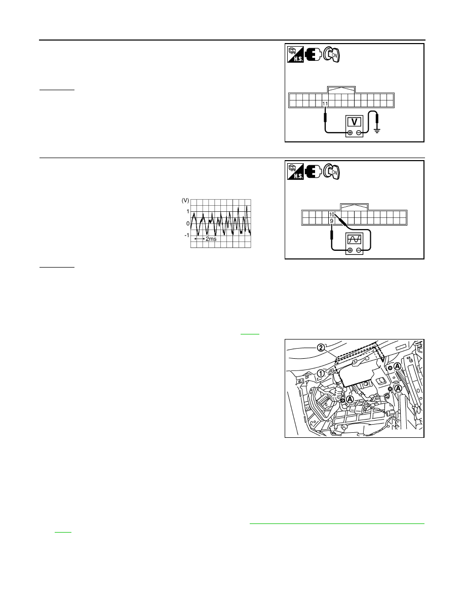
Check voltage between TEL adapter unit harness connector
M102 terminal 11 and ground.
OK or NG
OK
>> GO TO 4.
NG
>> Replace audio unit.
4.
CHECK TEL VOICE SIGNAL
1.
Check signal between TEL adapter unit harness connector
M102 terminals 9 and 10.
OK or NG
OK
>> Replace audio unit.
NG
>> Replace TEL adapter unit.
Removal and Installation of TEL Adapter Unit
INFOID:0000000001328798
REMOVAL
1.
Remove instrument passenger lower panel. Refer to
.
2.
Remove screws (A) with power tool and remove display control
unit (1)and TEL adapter unit (2).
3.
Remove TEL adapter unit screws, display control unit screws, and remove brackets.
INSTALLATION
Installation is the reverse order of removal.
Removal and Installation for TEL Antenna
INFOID:0000000001328799
REMOVAL
1.
Remove TEL adapter unit, display control unit. Refer to
AV-172, "Removal and Installation of TEL Adapter
.
11 – Ground
: Approx. 5 V
SKIB7352E
9 – 10:
When giving a voice
SKIB7353E
SKIB3609E
SKIB8667E

TELEPHONE
AV-173
< SERVICE INFORMATION >
C
D
E
F
G
H
I
J
L
M
A
B
AV
N
O
P
2.
Remove screws (A) and remove TEL antenna (1) from bracket.
INSTALLATION
Installation is the reverse order of removal.
Removal and Installation of Microphone
INFOID:0000000001328800
REMOVAL
1.
Remove roof console. Refer to
2.
Remove screws (A) and remove microphone (1) from roof con-
sole.
INSTALLATION
Installation is the reverse order of removal.
SKIB8669E
SKIB8670E
Нет комментариевНе стесняйтесь поделиться с нами вашим ценным мнением.
Текст