Infiniti FX35 / FX45. Manual — part 309
REAR VIEW MONITOR
DI-111
< SERVICE INFORMATION >
C
D
E
F
G
H
I
J
L
M
A
B
DI
N
O
P
NG
>> Repair or replace power supply and ground circuit.
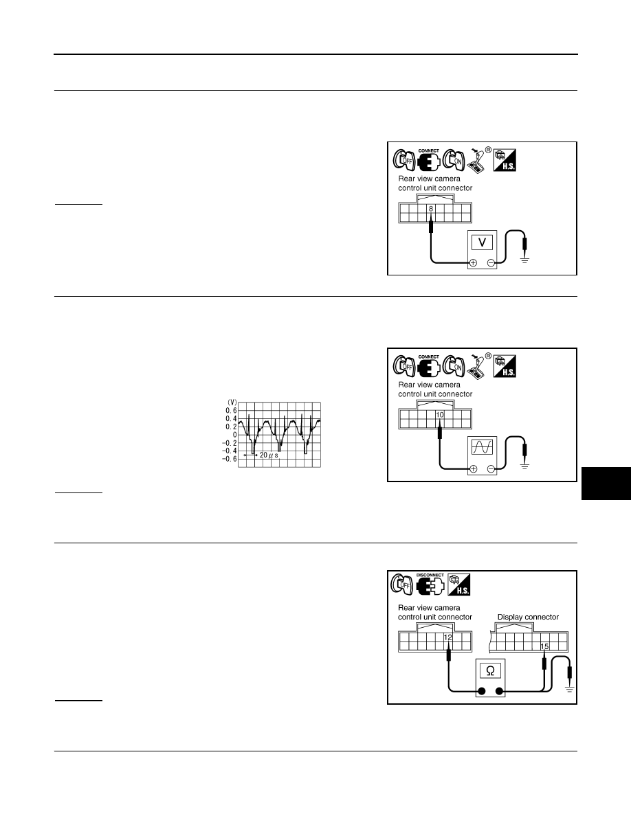
9.
CHECK REAR VIEW CAMERA CONTROL UNIT OUTPUT SIGNAL
1.
Turn ignition switch OFF.
2.
Connect rear view camera control unit connector.
3.
Turn ignition switch ON.
4.
Shift A/T selector lever to R position.
5.
Check voltage between rear view camera control unit harness
connector M48 terminal 8 and ground.
OK or NG
OK
>> GO TO 10.
NG
>> Replace rear view camera control unit.
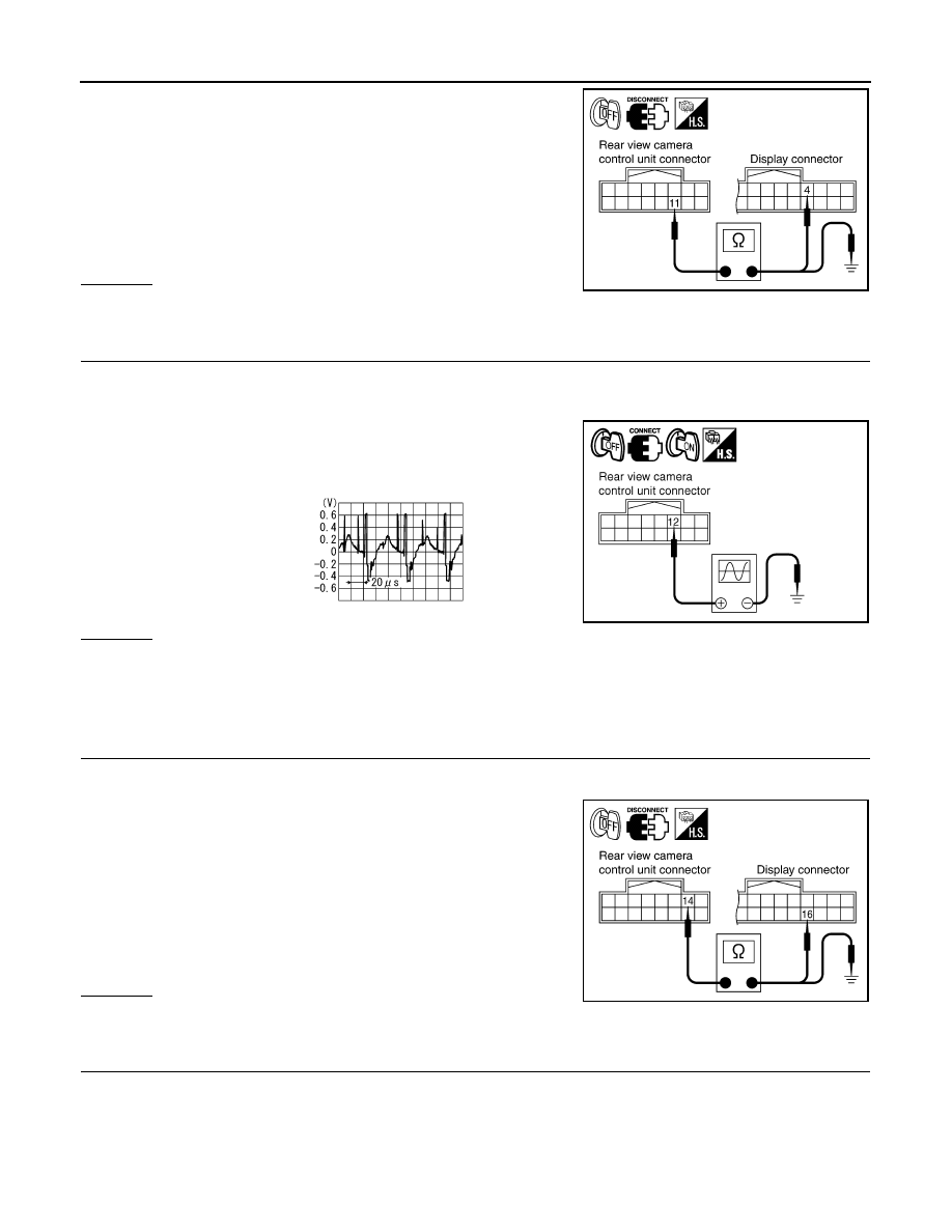
10.
CHECK REAR VIEW CAMERA SIGNAL
1.
Turn ignition switch OFF.
2.
Connect rear view camera connector.
3.
Turn ignition switch ON.
4.
Shift A/T selector lever to R position.
5.
Check voltage signal between rear view camera control unit har-
ness connector M48 terminal 10 and ground.
OK or NG
OK
>> GO TO 11.
NG
>> Replace rear view camera.
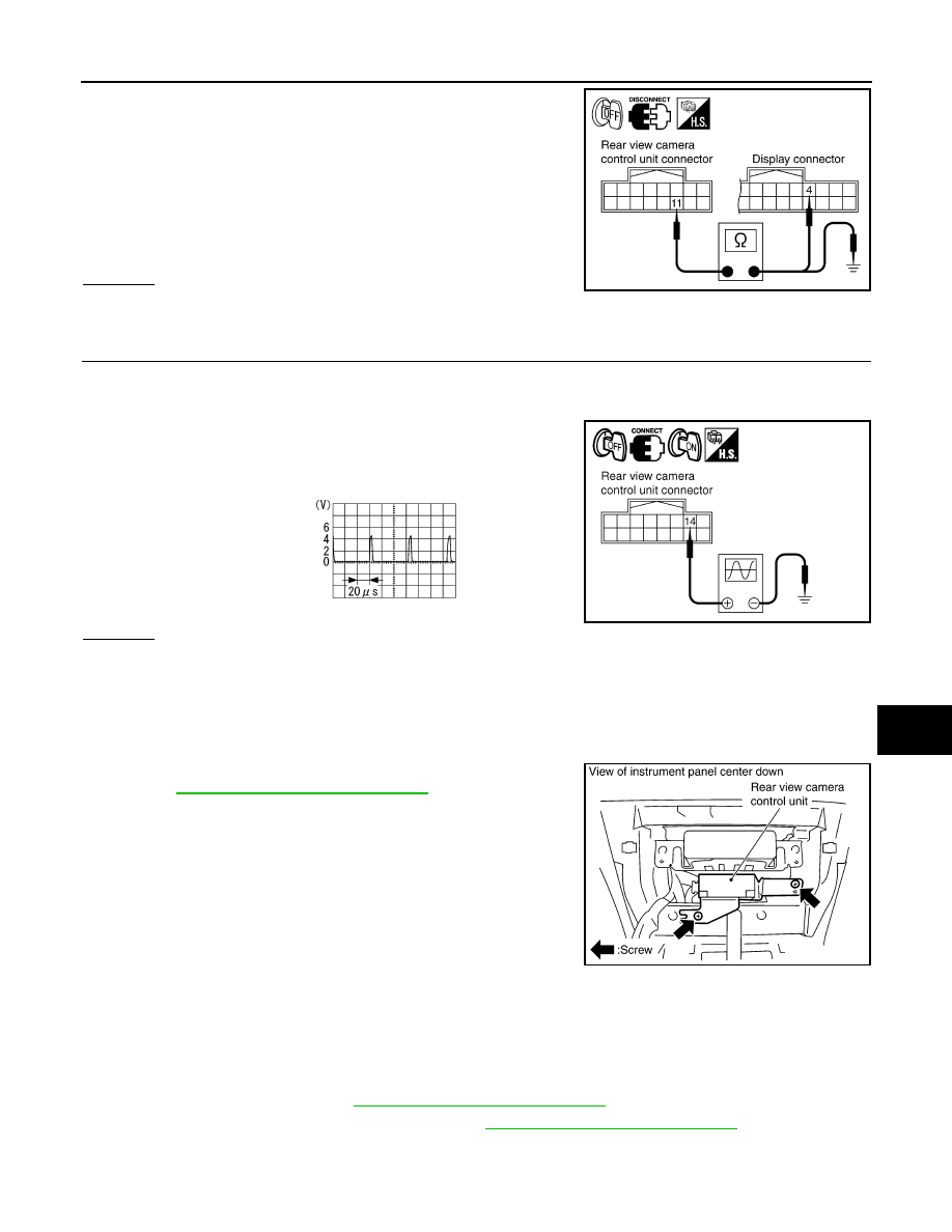
11.
CHECK COMPOSITE SIGNAL CIRCUIT
1.
Turn ignition switch OFF.
2.
Disconnect rear view camera control unit connector and display connector.
3.
Check continuity between rear view camera control unit harness
connector M48 terminal 12 and display harness connector M63
terminal 15.
4.
Check continuity between rear view camera control unit harness
connector M48 terminal 12 and ground.
OK or NG
OK
>> GO TO 12.
NG
>> Repair harness or connector.
12.
CHECK COMPOSITE SIGNAL GROUND CIRCUIT
8 – Ground
: Approx. 6 V
PKIB3581E
10 – Ground:
PKIB3582E
SKIA4894E
12 – 15
: Continuity should exist.
12 – Ground
: Continuity should not exist.
SKIB0482E
DI-112
< SERVICE INFORMATION >
REAR VIEW MONITOR
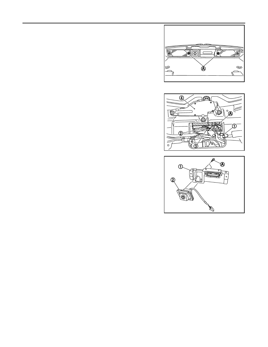
1.
Check continuity between rear view camera control unit harness
connector M48 terminal 11 and display harness connector M63
terminal 4.
2.
Check continuity between rear view camera control unit harness
connector M48 terminal 11 and ground.
OK or NG
OK
>> GO TO 13.
NG
>> Repair harness or connector.
13.
CHECK COMPOSITE SIGNAL
1.
Connect rear view camera control unit connector and display connector.
2.
Turn ignition switch ON.
3.
Shift A/T selector lever to R position.
4.
Check voltage signal between rear view camera control unit har-
ness connector M48 terminal 12 and ground.
OK or NG
OK
>> Replace display.
NG
>> Replace rear view camera control unit.
The Rear View Image Is Distorted
INFOID:0000000001328538
1.
CHECK SYNCHRO SIGNAL OPEN OR SHORT CIRCUIT
1.
Turn ignition switch OFF.
2.
Disconnect rear view camera control unit connector and display connector.
3.
Check continuity between rear view camera control unit harness
connector M48 terminal 14 and display harness connector M63
terminal 16.
4.
Check continuity between rear view camera control unit harness
connector M48 terminal 14 and ground.
OK or NG
OK
>> GO TO 2.
NG
>> Repair harness or connector.
2.
CHECK COMPOSITE SIGNAL GROUND CIRCUIT
11 – 4
: Continuity should exist.
11 – Ground
: Continuity should not exist.
SKIA5102E
12 – Ground:
PKIB3583E
SKIA4896E
14 – 16
: Continuity should exist.
14 – Ground
: Continuity should not exist.
SKIA5101E
REAR VIEW MONITOR
DI-113
< SERVICE INFORMATION >
C
D
E
F
G
H
I
J
L
M
A
B
DI
N
O
P
1.
Check continuity between rear view camera control unit harness
connector M48 terminal 11 and display harness connector M63
terminal 4.
2.
Check continuity between rear view camera control unit harness
connector M48 terminal 11 and ground.
OK or NG
OK
>> GO TO 3.
NG
>> Repair harness or connector.
3.
CHECK REAR VIEW CONTROL UNIT SYNCHRO SIGNAL
1.
Connect rear view camera control unit connector and display connector.
2.
Turn ignition switch ON.
3.
Shift A/T selector lever to R position.
4.
Check voltage signal between rear view camera control unit har-
ness connector M48 terminal 14 and ground.
OK or NG
OK
>> Replace rear view camera control unit.
NG
>> Replace display.
Removal and Installation of Rear View Camera Control Unit
INFOID:0000000001328539
REMOVAL
1.
Remove instrument clock finisher and A/T console finisher.
Refer to
IP-10, "Component Parts Location"
.
2.
Remove screws (2), and remove rear view camera control unit.
INSTALLATION
Installation is the reverse order of removal.
Removal and Installation of Rear View Camera
INFOID:0000000001328540
REMOVAL
1.
Remove back door trim. Refer to
EI-47, "Component Parts Location"
.
2.
Remove back door outside finisher upper. Refer to
EI-35, "Component Parts Location"
.
11 – 4
: Continuity should exist.
11 – Ground
: Continuity should not exist.
SKIA5102E
14 – Ground:
PKIB3584E
SKIA5896E
SKIA5797E
DI-114
< SERVICE INFORMATION >
REAR VIEW MONITOR
3.
Remove licence lamp bolts (A).
4.
Disconnect rear wiper connector.
5.
Disconnect rear view camera connector (1) and back door
opener switch connector (2).
6.
Cut off back door module along the line (A).
7.
Remove back door opener switch and rear view camera assem-
bly (3).
• Rear wiper (4)
8.
Remove screws (A), and remove rear view camera (1) from
back door opener switch (2).
INSTALLATION
Installation is the reverse order of removal.
SKIB8490E
SKIB8491E
SKIB8492E
Нет комментариевНе стесняйтесь поделиться с нами вашим ценным мнением.
Текст