Infiniti FX35 / FX45. Manual — part 308
REAR VIEW MONITOR
DI-107
< SERVICE INFORMATION >
C
D
E
F
G
H
I
J
L
M
A
B
DI
N
O
P
DATA MONITOR
Side Distance Guideline Correction
INFOID:0000000001328535
This mode is used to modify the side distance guidelines if they are dislocated from the rear view monitor
image, because of variations of body/camera mounting conditions.
SIDE DISTANCE GUIDELINE CORRECTION PROCEDURE
1.
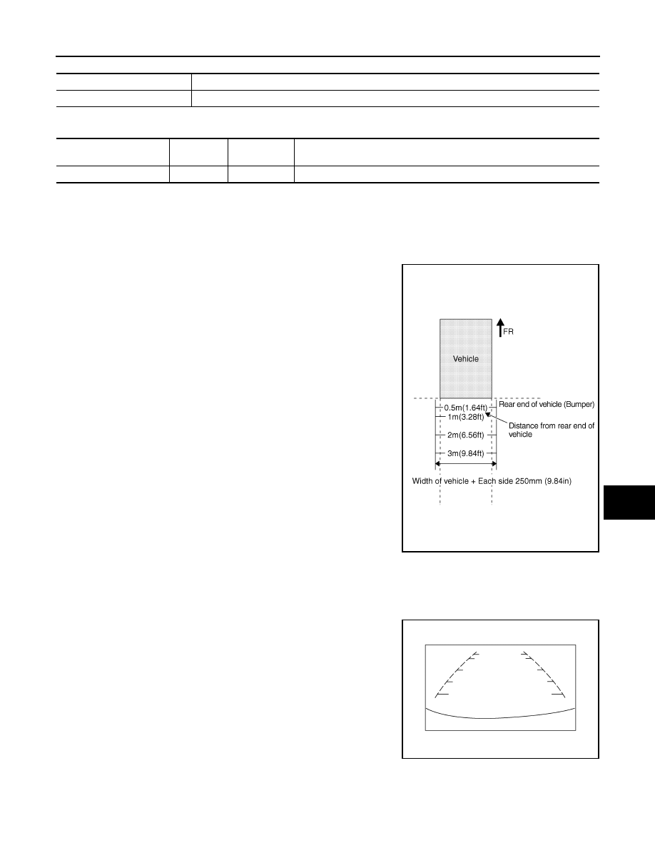
Create a correction line to modify the screen.
Draw lines on the rearward of the vehicle passing through the
following points: 0.25 m (9.84 in) from both sides of the vehicle,
and 0.5 m (1.64 ft), 1 m (3.28 ft), 2 m (6.56 ft), and 3 m (9.84 ft)
from the rear end of the bumper.
2.
Select “REARVIEW CAMERA” on CONSULT-III.
CAUTION:
Stop engine for the safety when correcting side distance guideline.
3.
Shift A/T selector lever to R position.
4.
Select “SELCT GUIDELINE PATTERN”.
5.
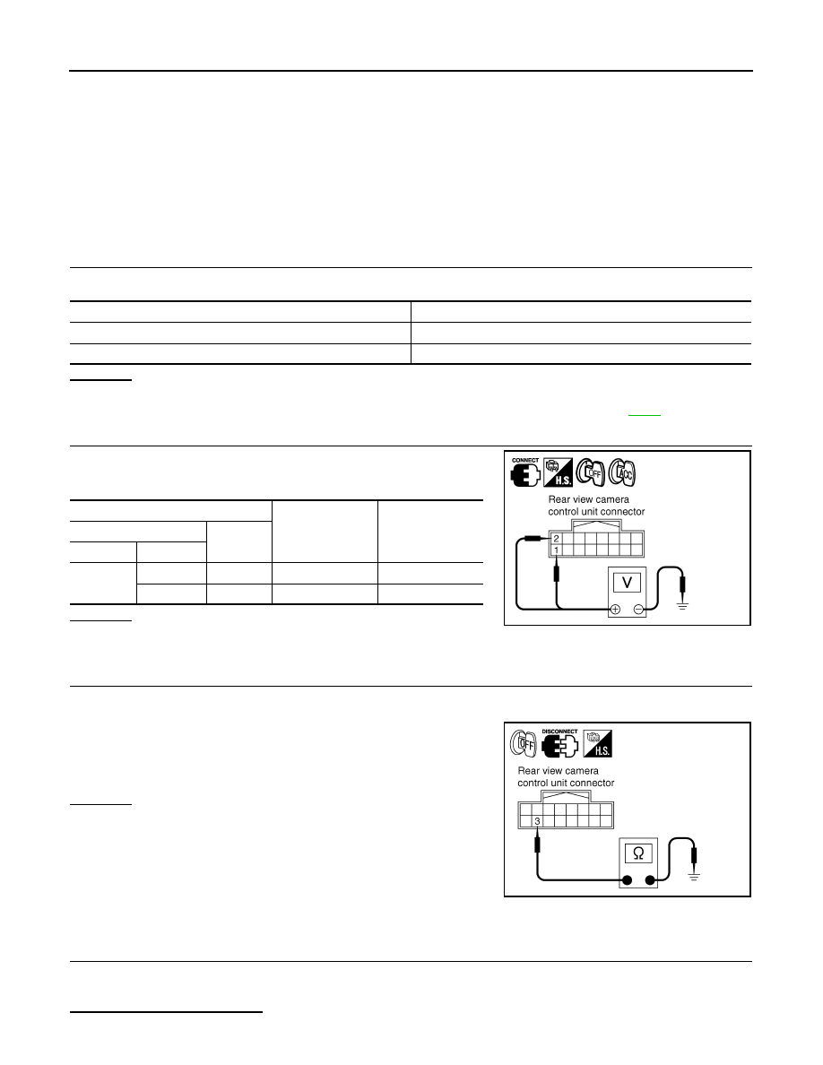
Select “UP” or “DOWN”, and select the guide line, “PATTERN NO. 0” or “PATTERN NO. 1”, which is the
closest to the corrected line.
SELCT GUIDELINE PATTERN
Side distance guideline is optional from two patterns.
ADJ GUIDELINE POSITION
Side distance guideline is adjustable toward up and down, right and left.
Display item [Unit]
ALL
SIGNALS
SELECTION
FROM MENU
Contents
R POSI SIG [On/Off]
X
X
Indicates [On/Off] condition of R range position signal input.
SKIB4106E
SKIA6103E
DI-108
< SERVICE INFORMATION >
REAR VIEW MONITOR
6.
Select “SAVE”, and confirm the guide line.
7.
Select “End”.
8.
Select “ADJ GUIDELINE POSITION”.
9.
Adjust the guide line selecting “X UP”, “X DOWN”, “Y UP” or “Y DOWN” so that the corrected line can fit
the guide line.
10. Touch “SAVE”, and confirm the guide line.
11. Touch “End” to finish correcting.
Power Supply and Ground Circuit Inspection
INFOID:0000000001328536
1.
CHECK FUSE
Make sure the fuses for rear view camera control unit is blown.
OK or NG
OK
>> GO TO 2.
NG
>> Be sure to eliminate cause of malfunction before installing new fuse. Refer to
.
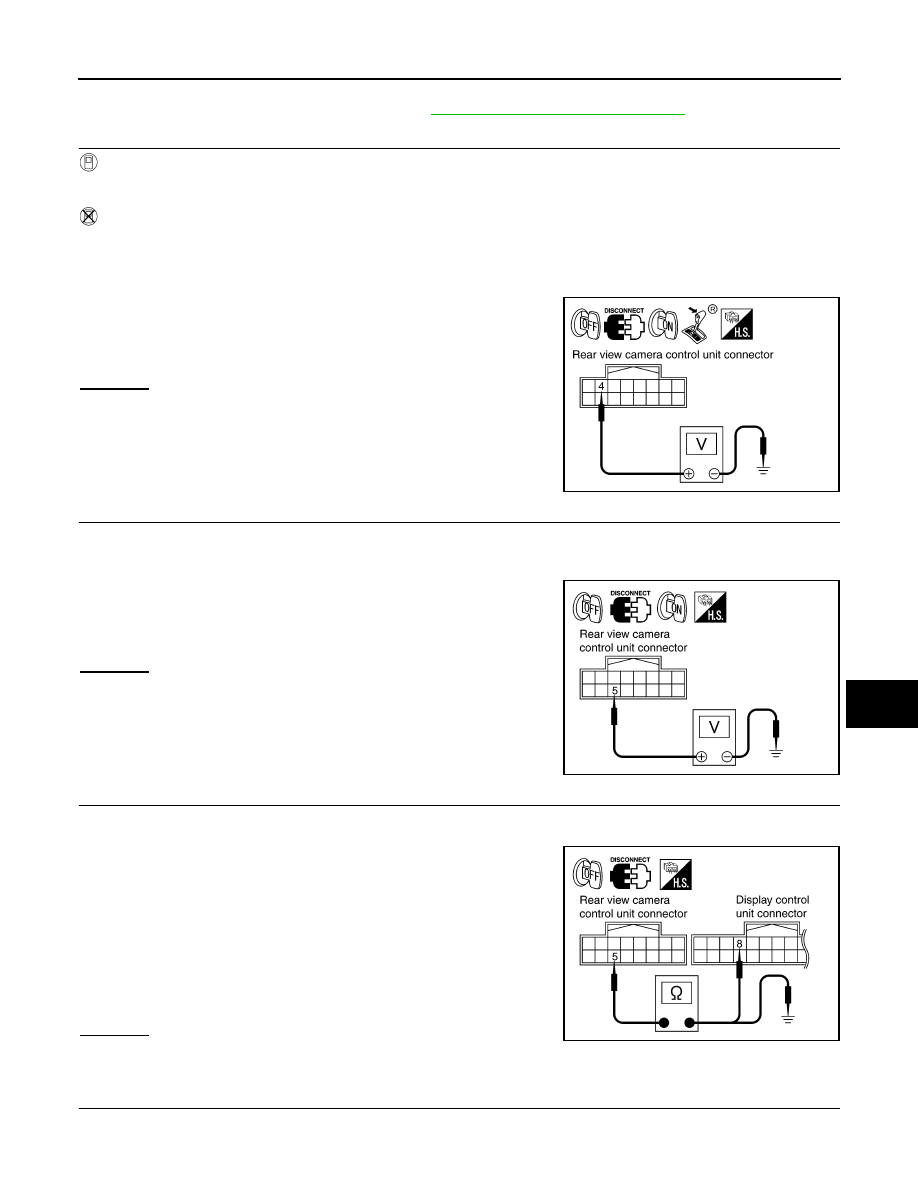
2.
CHECK POWER SUPPLY CIRCUIT
Check voltage between rear view camera control unit harness con-
nector M48 terminals 1, 2 and ground.
OK or NG
OK
>> GO TO 3.
NG
>> Check harness between rear view camera control unit and fuse.
3.
CHECK REAR VIEW CAMERA CONTROL UNIT GROUND CIRCUIT
1.
Turn ignition switch OFF.
2.
Disconnect rear view camera control unit connector.
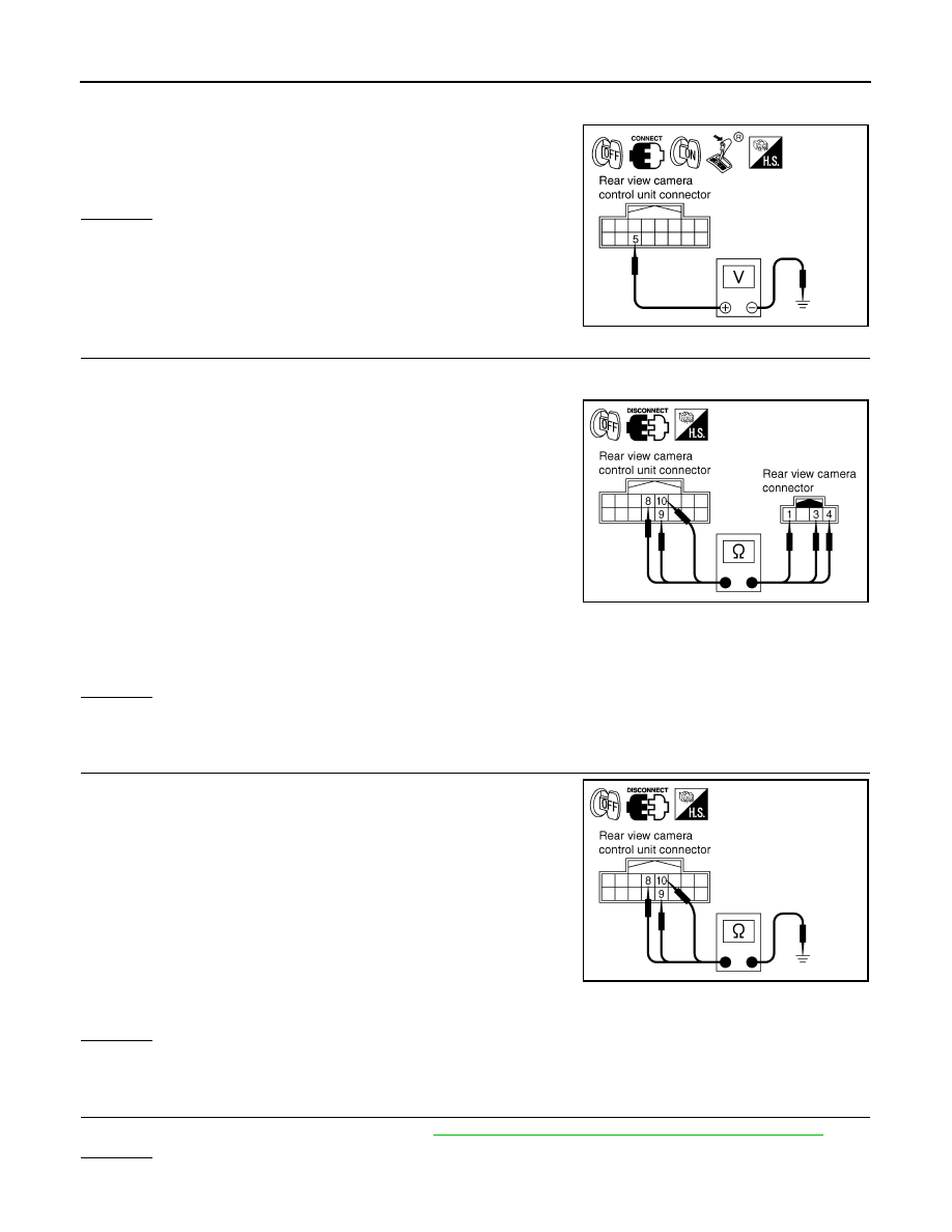
3.
Check continuity between rear view camera control unit harness
connector M48 terminal 3 and ground.
OK or NG
OK
>> INSPECTION END
NG
>> Repair harness or connector.
Rear View Is Not Displayed with the A/T Selector Lever in R-Position
INFOID:0000000001328537
1.
BACK-UP LAMP INSPECTION
1.
Turn ignition switch ON.
2.
Shift A/T selector lever to R position.
Does back-up lamp illuminate?
Power source
Fuse No.
Battery power supply
19
ACC power supply
6
Terminals
OFF
ACC
(+)
(–)
Connector
Terminal
M48
1
Ground
Battery voltage
Battery voltage
2
Ground
0 V
Battery voltage
PKIB3580E
3 – Ground
: Continuity should exist.
SKIA5081E
REAR VIEW MONITOR
DI-109
< SERVICE INFORMATION >
C
D
E
F
G
H
I
J
L
M
A
B
DI
N
O
P
YES
>> GO TO 2.
NO
>> Check back-up lamp system. Refer to
LT-116, "Wiring Diagram - BACK/L -"
in LT section.
2.
CHECK REVERSE POSITION INPUT SIGNAL
With CONSULT-III
1.
Select “Data Monitor” of “REARVIEW CAMERA”.
2.
Operate ignition switch with “R POSI SIG” of “Data Monitor” and check operate status.
Without CONSULT-III
1.
Turn ignition switch OFF.
2.
Disconnect rear view camera control unit connector.
3.
Turn ignition switch ON.
4.
Shift A/T selector lever to R position.
5.
Check voltage between rear view camera control unit harness
connector M48 terminal 4 and ground.
OK or NG
OK
>> GO TO 3.
NG
>> Check harness between rear view camera control unit
and back-up lamp relay.
3.
CHECK DISPLAY CONTROL UNIT OUTPUT SIGNAL
1.
Turn ignition switch OFF.
2.
Disconnect rear view camera control unit connector.
3.
Turn ignition switch ON.
4.
Check voltage between rear view camera control unit harness
connector M48 terminal 5 and ground.
OK or NG
OK
>> GO TO 5.
NG
>> GO TO 4.
4.
CHECK DISPLAY CONTROL UNIT CIRCUIT
1.
Turn ignition switch OFF.
2.
Disconnect display control unit connector.
3.
Check continuity between rear view camera control unit harness
connector M48 terminal 5 and display control unit harness con-
nector M75 terminal 8.
4.
Check continuity between rear view camera control unit harness
connector M48 terminal 5 and ground.
OK or NG
OK
>> Replace display control unit.
NG
>> Repair harness or connector.
5.
CHECK CONTROL 1 SIGNAL
1.
Turn ignition switch OFF.
2.
Connect rear view camera control unit connector.
4 – Ground
: Battery voltage
SKIA5086E
5 – Ground
: Approx. 5 V
SKIA7148E
5 – 8
: Continuity should exist.
5 – Ground
: Continuity should not exist.
SKIA7149E
DI-110
< SERVICE INFORMATION >
REAR VIEW MONITOR
3.
Turn ignition switch ON.
4.
Shift A/T selector lever to R position.
5.
Check voltage between rear view camera control unit harness
connector M48 terminal 5 and ground.
OK or NG
OK
>> GO TO 6.
NG
>> Replace rear view camera control unit.
6.
CHECK REAR VIEW CAMERA OPEN CIRCUIT
1.
Turn ignition switch OFF.
2.
Disconnect rear view camera connector.
3.
Check continuity between rear view camera control unit harness
connector M48 terminal 8 and rear view camera harness con-
nector D108 terminal 1.
4.
Check continuity between rear view camera control unit harness
connector M48 terminal 9 and rear view camera harness con-
nector D108 terminal 4.
5.
Check continuity between rear view camera control unit harness
connector M48 terminal 10 and rear view camera harness connector D108 terminal 3.
OK or NG
OK
>> GO TO 7.
NG
>> Repair harness or connector.
7.
CHECK REAR VIEW CAMERA SHORT CIRCUIT
1.
Check continuity between rear view camera control unit harness
connector M48 terminal 8 and ground.
2.
Check continuity between rear view camera control unit harness
connector M48 terminal 9 and ground.
3.
Check continuity between rear view camera control unit harness
connector M48 terminal 10 and ground.
OK or NG
OK
>> GO TO 8.
NG
>> Repair harness on connector.
8.
CHECK POWER SUPPLY AND GROUND CIRCUIT
Check power supply and ground circuit. Refer to
DI-108, "Power Supply and Ground Circuit Inspection"
OK or NG
OK
>> GO TO 9.
5 – Ground
: Approx. 0 V
SKIA7150E
8 – 1
: Continuity should exist.
9 – 4
: Continuity should exist.
10 – 3
: Continuity should exist.
SKIA5095E
8 – Ground
: Continuity should not exist.
9 – Ground
: Continuity should not exist.
10 – Ground
: Continuity should not exist.
SKIA5098E
Нет комментариевНе стесняйтесь поделиться с нами вашим ценным мнением.
Текст