Infiniti FX35 / FX45. Manual — part 382
DTC P0172, P0175 FUEL INJECTION SYSTEM FUNCTION
EC-289
< SERVICE INFORMATION >
[VQ35DE]
C
D
E
F
G
H
I
J
K
L
M
A
EC
N
P
O
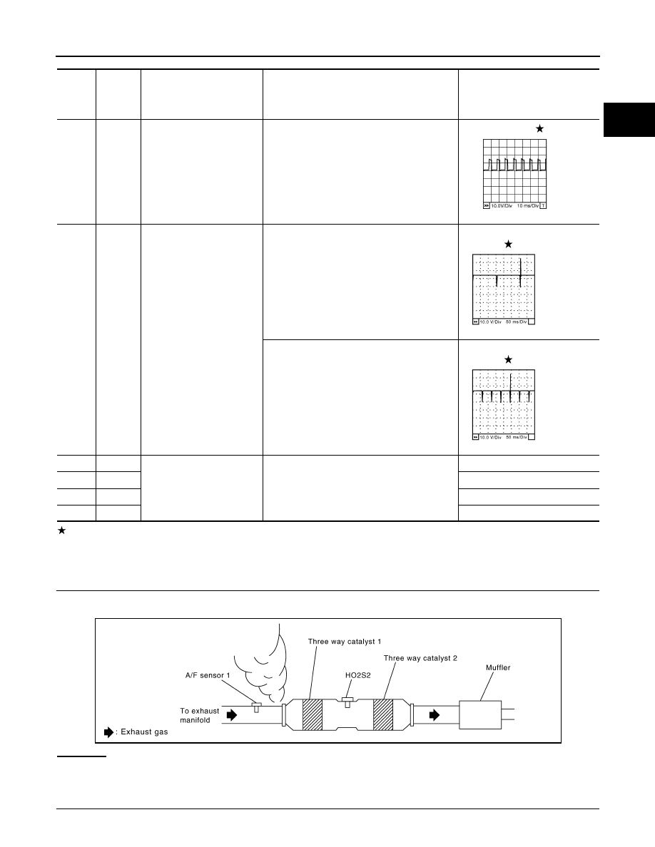
: Average voltage for pulse signal (Actual pulse signal can be confirmed by oscilloscope.)
Diagnosis Procedure
INFOID:0000000001326108
1.
CHECK EXHAUST GAS LEAK
1.
Start engine and run it at idle.
2.
Listen for an exhaust gas leak before three way catalyst 1.
OK or NG
OK
>> GO TO 2.
NG
>> Repair or replace.
2.
CHECK FOR INTAKE AIR LEAK
TER-
MI-
NAL
NO.
WIRE
COLOR
ITEM
CONDITION
DATA (DC Voltage)
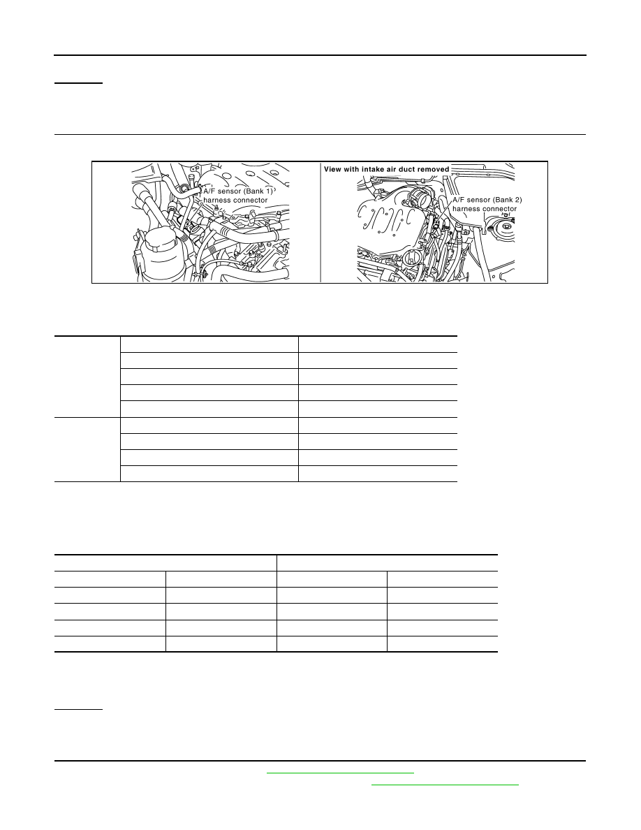
24
L
A/F sensor 1 heater
(bank 2)
[Engine is running]
• Warm-up condition
• Idle speed
Approximately 5V
40
41
42
LG
B
P
Fuel injector No. 6
Fuel injector No. 4
Fuel injector No. 2
[Engine is running]
• Warm-up condition
• Idle speed
NOTE:
The pulse cycle changes depending on rpm
at idle
BATTERY VOLTAGE
(11 - 14V)
[Engine is running]
• Warm-up condition
• Engine speed: 2,000 rpm
BATTERY VOLTAGE
(11 - 14V)
57
G
A/F sensor 1 (bank 2)
[Engine is running]
• Warm-up condition
• Idle speed
Approximately 2.6V
58
Y
Approximately 2.3V
76
P
Approximately 3.1V
77
BR
Approximately 2.3V
PBIB1584E
SEC984C
SEC985C
PBIB1922E
EC-290
< SERVICE INFORMATION >
[VQ35DE]
DTC P0172, P0175 FUEL INJECTION SYSTEM FUNCTION
Listen for an intake air leak after the mass air flow sensor.
OK or NG
OK
>> GO TO 3.
NG
>> Repair or replace.
3.
CHECK AIR FUEL RATIO (A/F) SENSOR 1 INPUT SIGNAL CIRCUIT
1.
Turn ignition switch OFF.
2.
Disconnect corresponding A/F sensor 1 harness connector.
3.
Disconnect ECM harness connector.
4.
Check harness continuity between the following terminals.
Refer to Wiring Diagram.
5.
Check harness continuity between the following terminals and ground.
Refer to Wiring Diagram.
6.
Also check harness for short to ground and short to power.
OK or NG
OK
>> GO TO 4.
NG
>> Repair open circuit or short to ground or short to power in harness or connectors.
4.
CHECK FUEL PRESSURE
1.
Release fuel pressure to zero. Refer to
.
2.
Install fuel pressure gauge and check fuel pressure. Refer to
Bank 1
A/F sensor 1 terminal
ECM terminal
1
16
2
75
5
35
6
56
Bank 2
1
76
2
77
5
57
6
58
Continuity should exist.
Bank 1
Bank 2
A/F sensor 1 terminal
ECM terminal
A/F sensor 1 terminal
ECM terminal
1
16
1
76
2
75
2
77
5
35
5
57
6
56
6
58
Continuity should not exist.
PBIB2190E
DTC P0172, P0175 FUEL INJECTION SYSTEM FUNCTION
EC-291
< SERVICE INFORMATION >
[VQ35DE]
C
D
E
F
G
H
I
J
K
L
M
A
EC
N
P
O
OK or NG
OK
>> GO TO 6.
NG
>> GO TO 5.
5.
DETECT MALFUNCTIONING PART
Check the following.
• Fuel pump and circuit (Refer to
.)
• Fuel pressure regulator (Refer to
.)
>> Repair or replace.
6.
CHECK MASS AIR FLOW SENSOR
With CONSULT-III
1.
Install all removed parts.
2.
Check “MASS AIR FLOW” in “DATA MONITOR” mode with CONSULT-III.
With GST
1.
Install all removed parts.
2.
Check mass air flow sensor signal in Service $01 with GST.
OK or NG
OK (With CONSULT-III)>>GO TO 7.
OK (Without CONSULT-III)>>GO TO 8.
NG
>> Check connectors for rusted terminals or loose connections in the mass air flow sensor circuit or
ground. Refer to
.
7.
CHECK FUNCTION OF FUEL INJECTOR
With CONSULT-III
1.
Start engine.
2.
Perform “POWER BALANCE” in “ACTIVE TEST” mode with CONSULT-III.
3.
Make sure that each circuit produces a momentary engine speed drop.
OK or NG
OK
>> GO TO 10.
NG
>> Perform trouble diagnosis for FUEL INJECTOR, refer to
8.
CHECK FUNCTION OF FUEL INJECTOR-I
Without CONSULT-III
1.
Stop engine.
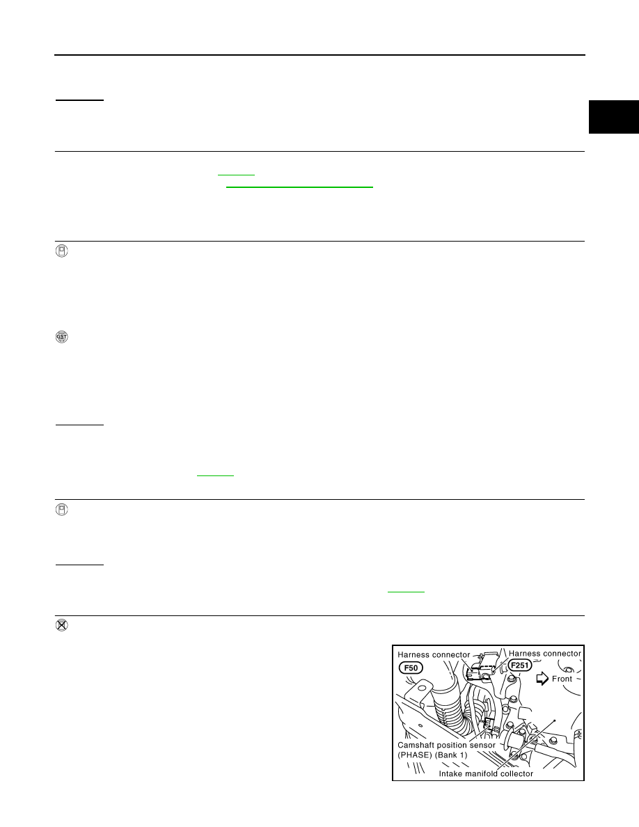
2.
Disconnect harness connector F50, F251
3.
Turn ignition switch ON.
At idling: Approximately 350 kPa (3.57 kg/cm
2
, 51 psi)
2.0 - 6.0 g·m/sec:
at idling
7.0 - 20.0 g·m/sec:
at 2,500 rpm
2.0 - 6.0 g·m/sec:
at idling
7.0 - 20.0 g·m/sec:
at 2,500 rpm
PBIB2624E
EC-292
< SERVICE INFORMATION >
[VQ35DE]
DTC P0172, P0175 FUEL INJECTION SYSTEM FUNCTION
4.
Check voltage between harness connector F50 terminal 5 and
ground.
5.
Turn ignition switch OFF.
6.
Disconnect ECM harness connector.
7.
Check harness continuity between harness connector F50 and
ECM as follows.
Refer to Wiring Diagram.
8.
Also check harness for short to ground and short to power.
OK or NG
OK
>> GO TO 9.
NG
>> Perform trouble diagnosis for FUEL INJECTOR, refer to
.
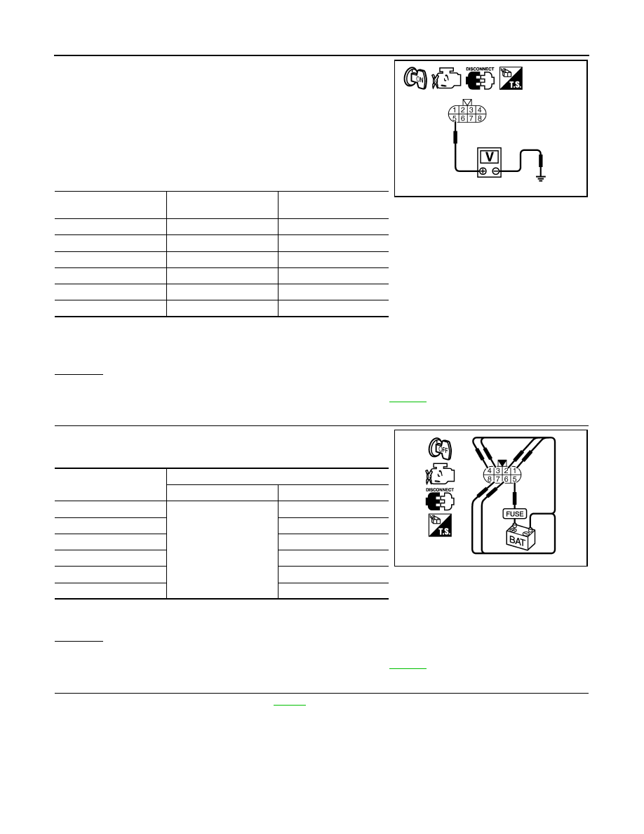
9.
CHECK FUNCTION OF FUEL INJECTOR-II
Provide battery voltage between harness connector F251 as follows
and then interrupt it. Listen to each fuel injector operating sound.
OK or NG
OK
>> GO TO 10.
NG
>> Perform trouble diagnosis for FUEL INJECTOR, refer to
.
10.
CHECK FUEL INJECTOR
1.
Remove fuel injector assembly. Refer to
Keep fuel hose and all fuel injectors connected to fuel injector gallery.
2.
Confirm that the engine is cooled down and there are no fire hazards near the vehicle.
3.
Reconnect all harness connectors disconnected.
4.
Disconnect all fuel injector harness connectors.
5.
Disconnect all ignition coil harness connectors.
6.
Prepare pans or saucers under each fuel injectors.
7.
Crank engine for about 3 seconds.
Make sure fuel does not drip from fuel injector.
Voltage: Battery voltage
Cylinder
Harness connector F50
terminal
ECM terminal
1
6
23
2
4
42
3
2
22
4
3
41
5
1
21
6
7
40
Continuity should exist.
PBIB2323E
Cylinder
Harness connector F251 terminal
(+)
(–)
1
5
6
2
4
3
2
4
3
5
1
6
7
Operating sound should exist.
PBIB2497E
Нет комментариевНе стесняйтесь поделиться с нами вашим ценным мнением.
Текст