Infiniti FX35 / FX45. Manual — part 863
REAR PROPELLER SHAFT
PR-7
< SERVICE INFORMATION >
C
E
F
G
H
I
J
K
L
M
A
B
PR
N
O
P
REAR PROPELLER SHAFT
On-Vehicle Inspection
INFOID:0000000001327469
APPEARANCE AND NOISE INSPECTION
• Check the propeller shaft tube surface for dents or cracks. If damaged, replace propeller shaft assembly.
• If center bearing is noisy or damaged, replace center bearing.
PROPELLER SHAFT VIBRATION
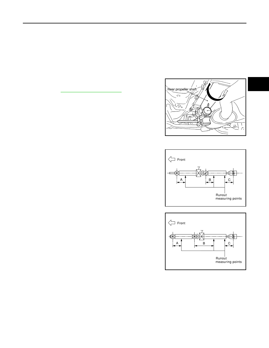
If vibration is present at high speed, inspect propeller shaft runout first.
1.
Measure propeller shaft runout at runout measuring points by
rotating final drive companion flange with hands. For measuring
point, refer to
.
2.
If runout still exceeds specifications, separate propeller shaft at
final drive companion flange; then rotate companion flange 60,
120, 180, 240, 300 degrees and install propeller shaft.
3.
Check runout again. If runout still exceeds specifications,
replace propeller shaft assembly.
4.
Check the vibration by driving vehicle.
Propeller Shaft Runout Measuring Point
• 2WD models (3S80A-1VL107 type)
• AWD models (3F80A-1VL107 type)
Propeller shaft runout limit
: 0.8 mm (0.031 in)
SDIA1781E
Dimension
A: 192 mm (7.56 in)
B: 190 mm (7.48 in)
C: 185 mm (7.28 in)
SDIA1581E
Dimension
A: 162 mm (6.38 in)
B: 245 mm (9.65 in)
C: 185 mm (7.28 in)
SDIA1779E
PR-8
< SERVICE INFORMATION >
REAR PROPELLER SHAFT
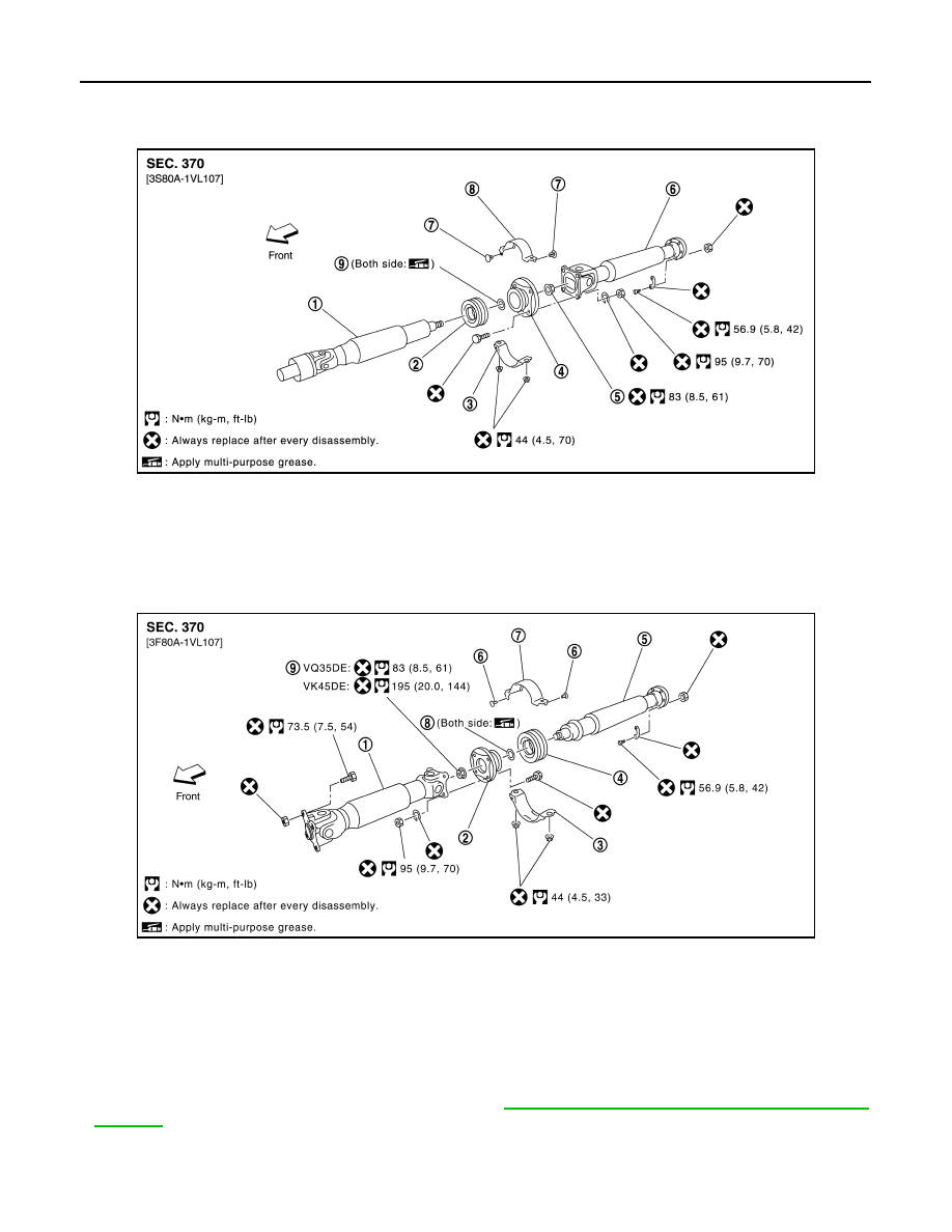
Component
INFOID:0000000001327470
2WD Models
AWD Models
NOTE:
• The joint cannot be disassembled.
• The center bearing can be disassembled. Refer to
PR-11, "Disassembly and Assembly of Center
PDIA0687E
1.
Propeller shaft (1st shaft)
2.
Center bearing assembly
3.
Center bearing mounting bracket
(Lower)
4.
Center flange
5.
Lock nut
6.
Propeller shaft (2nd shaft)
7.
Clip
8.
Center bearing mounting bracket
(Upper)
9.
Washer
PDIA0688E
1.
Propeller shaft (1st shaft)
2.
Center flange
3.
Center bearing mounting bracket
(Lower)
4.
Center bearing assembly
5.
Propeller shaft (2nd shaft)
6.
Clip
7.
Center bearing mounting bracket
(Upper)
8.
Washer
9.
Lock nut
REAR PROPELLER SHAFT
PR-9
< SERVICE INFORMATION >
C
E
F
G
H
I
J
K
L
M
A
B
PR
N
O
P
Removal and Installation
INFOID:0000000001327471
REMOVAL
1.
Move the A/T select lever to N position and release the parking brake.
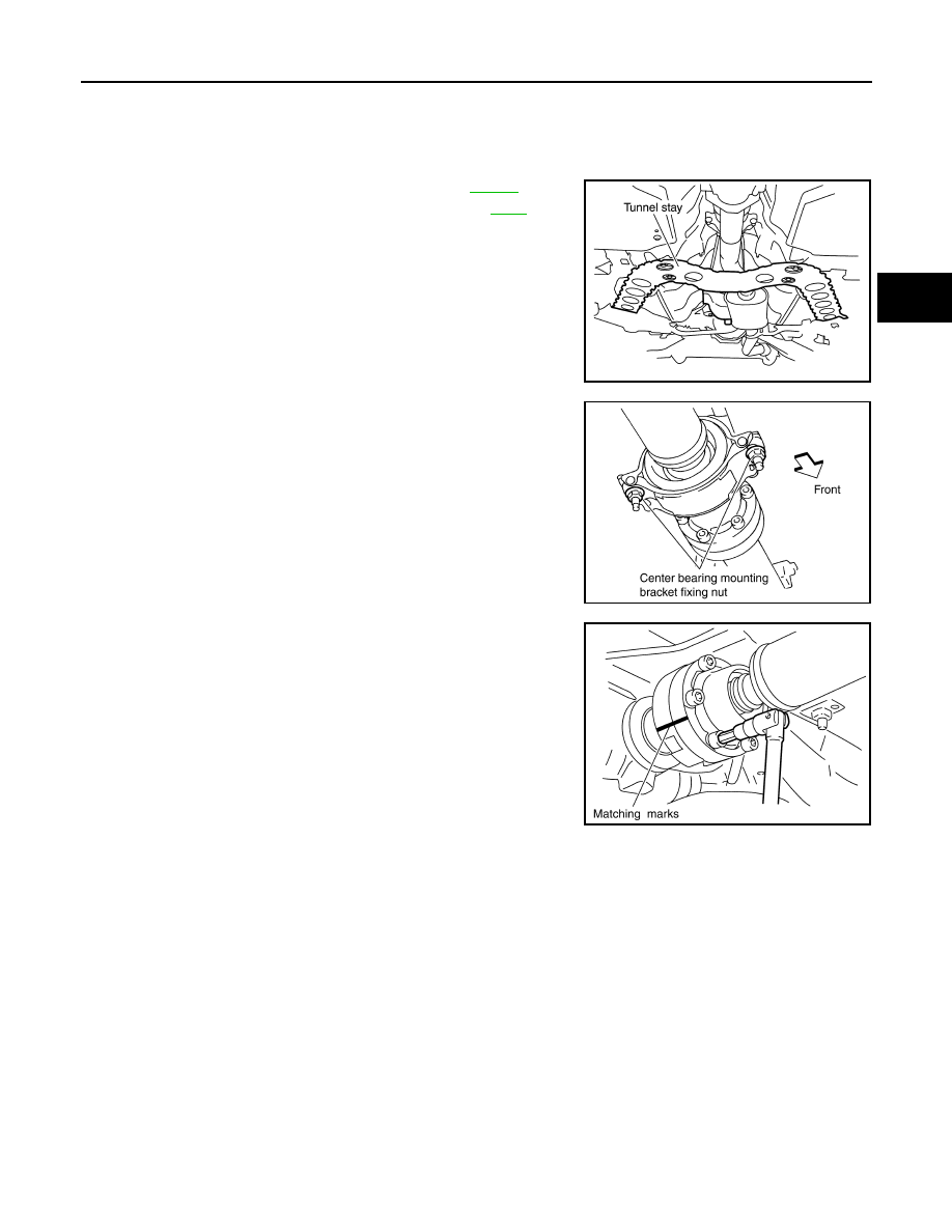
2.
Remove the tunnel stay with power tool. Refer to
3.
Remove the center muffler with power tool. Refer to
4.
Loosen mounting nuts of center bearing mounting brackets with
power tool.
CAUTION:
Tighten mounting nuts temporarily.
5.
For 2WD models
• Put matching marks on propeller shaft rebro joint with final
drive companion flange.
CAUTION:
For matching mark, use paint. Never damage propeller
shaft and companion flange.
For AWD models
• Put matching marks on propeller shaft flange yoke with trans-
fer companion flange and on rebro joint with final drive com-
panion flange.
CAUTION:
For matching mark, use paint. Never damage propeller
shaft flange yoke, rebro joint and companion flanges.
6.
Remove propeller shaft fixing bolts and nuts.
7.
Remove center bearing mounting bracket fixing nuts.
8.
Remove propeller shaft.
CAUTION:
If constant velocity joint was bent during propeller shaft assembly removal, installation, or trans-
portation, its boot may be damaged. Wrap boot interference area to metal part with shop cloth or
rubber to protect boot from breakage.
INSPECTION
PDIA0744E
PDIA0402E
PDIA0470E
PR-10
< SERVICE INFORMATION >
REAR PROPELLER SHAFT
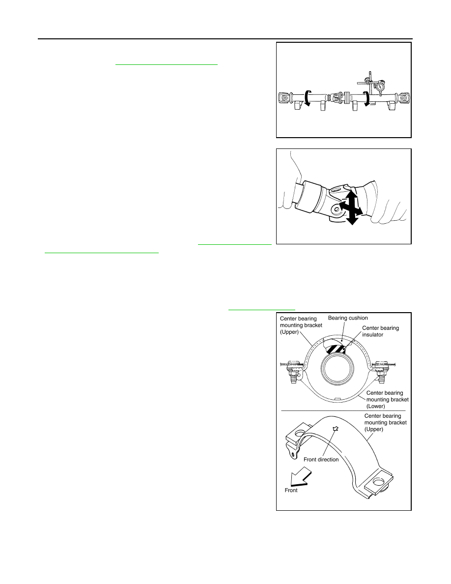
• Inspect propeller shaft runout at measuring points. If runout
exceeds specifications, replace propeller shaft assembly. For mea-
suring point, refer to
.
• As shown in the figure, while fixing yoke on one side, check axial
play of joint. If outside the standard, replace relevant propeller
shaft.
• Check propeller shaft for bend and damage. If damage is detected,
replace relevant propeller shaft.
CAUTION:
Never disassemble joints.
• Check center bearing for noise and damage. If noise or damage is
detected, replace center bearing. Refer to
and Assembly of Center Bearing"
INSTALLATION
Note the following, and install in the reverse order of removal.
CAUTION:
Avoid damaging the rebro joint boot, protect it with a shop towel or equivalent.
• Align matching marks to install propeller shaft to final drive and transfer (AWD models only) companion
flanges, and then tighten to specified torque. Refer to
.
• Install center bearing mounting bracket (Upper) with its arrow mark
facing forward.
• Adjust position of mounting bracket sliding back and forth to pre-
vent play in thrust direction of center bearing insulator. Install
bracket to vehicle.
• After assembly, perform a driving test to check propeller shaft
vibration. If vibration occurred, separate propeller shaft from final
drive. Reinstall companion flange after rotating it by 60, 120, 180,
240, 300 degrees. Then perform driving test and check propeller
shaft vibration again at each point.
• If propeller shaft or final drive has been replaced, connect them as follows:
Propeller shaft runout limit
: 0.8 mm (0.031 in)
SDIA2071E
Journal axial play
: 0 mm (0 in)
SPD874
PDIA0017E
Нет комментариевНе стесняйтесь поделиться с нами вашим ценным мнением.
Текст