Infiniti FX35 / FX45. Manual — part 864

REAR PROPELLER SHAFT
PR-11
< SERVICE INFORMATION >
C
E
F
G
H
I
J
K
L
M
A
B
PR
N
O
P
1.
Install the propeller shaft while aligning its matching mark A with
the matching mark B on the joint as close as possible.
2.
Tighten the joint bolts to the specified torque. Refer to
.
CAUTION:
Never reuse the bolts, nuts and washers.
Disassembly and Assembly of Center Bearing
INFOID:0000000001327472
DISASSEMBLY
1.
Put matching marks on propeller shaft and center flange, then
disassemble the 1st and 2nd propeller shaft.
CAUTION:
For matching mark, use paint. Never damage the propeller
shaft flange and center flange.
2.
Put matching marks onto the center flange and propeller shaft
end as shown.
CAUTION:
For matching mark, use paint. Never damage propeller shaft
end and center flange.
3.
Hold the center flange using the flange wrench, and remove the
lock nut.
4.
Remove the center flange using a commercial available bearing
puller then remove washer.
SDIA2049E
SDIA1538E
SDIA1539E
Tool number
: KV40104000 (
—
)
SDIA1540E
PR-12
< SERVICE INFORMATION >
REAR PROPELLER SHAFT
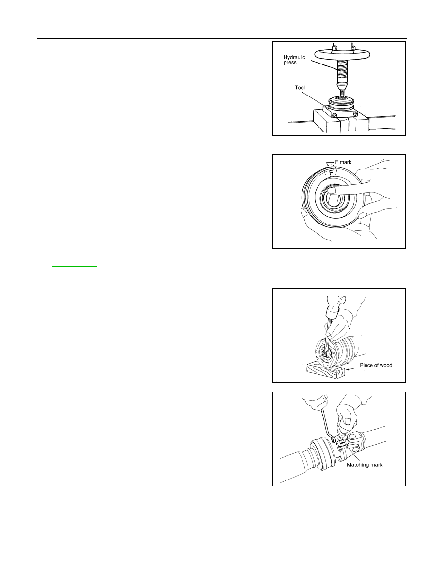
5.
Press out the center bearing using the puller and hydraulic
press.
ASSEMBLY
1.
For the 3S80A-1VL107 (VQ35DE/2WD) and 3F80A-1VL107
(VK45DE/AWD) type
• Install the center bearing with its “F” mark facing the front of
the vehicle.
For the 3F80A-1VL107 (VQ35DE/AWD) type
• Install the center bearing with its “F” mark facing the rear of the
vehicle.
2.
Apply multi-purpose grease to the each face of the washer, then
install washer.
3.
Install the center flange onto the propeller shaft with aligning the
marks that are marked while removal.
4.
Install and tighten the lock nut to specified torque. Refer to
.
CAUTION:
Never use the lock nut.
5.
Place a piece of wood under the center flange, stake the lock
nut against the propeller shaft groove. [For the 3S80A-1VL107
(VQ35DE/2WD) and 3F80A-1VL107 (VQ35DE/AWD) type]
6.
Assemble the 1st and 2nd shaft propeller shafts while aligning
the matching marks that are marked during removal.
7.
Install and tighten the bolts/nuts and tighten them to specified
torque. Refer to
.
CAUTION:
Never reuse the bolts, nuts and washers.
Tool number
: ST30031000 (J-22912-01)
SDIA1541E
SDIA1542E
SDIA1543E
SDIA1538E
SERVICE DATA AND SPECIFICATIONS (SDS)
PR-13
< SERVICE INFORMATION >
C
E
F
G
H
I
J
K
L
M
A
B
PR
N
O
P
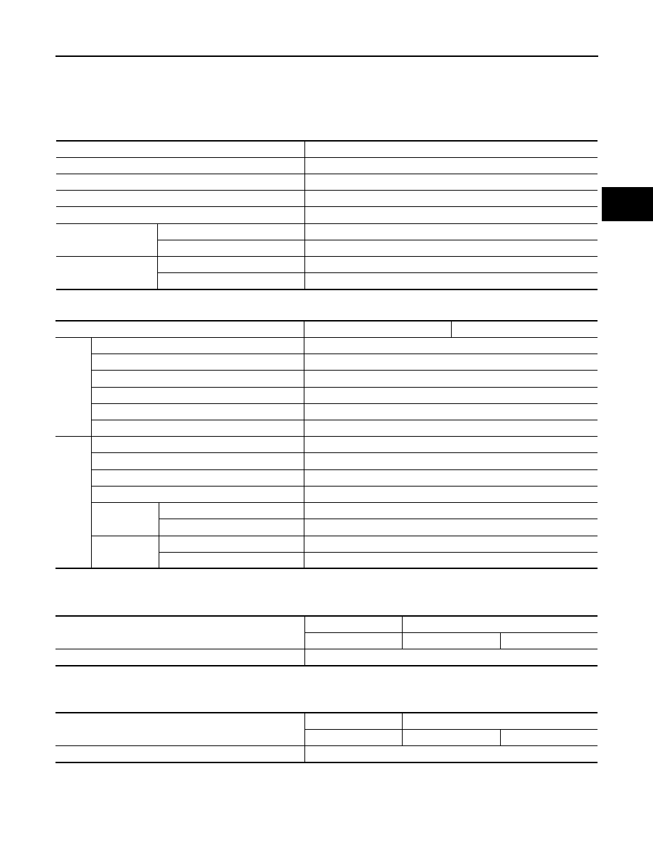
SERVICE DATA AND SPECIFICATIONS (SDS)
General Specification
INFOID:0000000001327473
2WD MODELS
AWD MODELS
Journal Axal Play
INFOID:0000000001327474
Unit: mm (in)
Propeller Shaft Runout
INFOID:0000000001327475
Unit : mm (in)
Applied model
VQ35DE
Propeller shaft model
3S80A-1VL107
Number of joints
3
Coupling method with transmission
Sleeve type
Coupling method with rear final drive
Rebro joint type
Shaft length
1st (Spider to spider)
795 mm (31.30 in)
2nd (Spider to rebro joint center)
681 mm (35.51 in)
Shaft outer diameter
1st
82.6 mm (3.25 in)
2nd
82.6 mm (3.25 in)
Applied model
VQ35DE
VK45DE
Front
Propeller shaft model
2S56A
Number of joints
2
Coupling method with transfer
Sleeve type
Coupling method with front final drive
Flange type
Shaft length (Spider to spider)
763 mm (30.04 in)
Shaft outer diameter
42.7 mm (1.68 in)
Rear
Propeller shaft model
3F80A-1VL107
Number of joints
3
Coupling method with transfer
Flange type
Coupling method with rear final drive
Rebro joint type
Shaft length
1st (Spider to spider)
399 mm (15.71 in)
2nd (Spider to rebro joint center)
753 mm (29.65 in)
Shaft outer di-
ameter
1st
82.6 mm (3.25 in)
2nd
82.6 mm (3.25 in)
Model
Front propeller shaft
Rear propeller shaft
2S56A
3S80A-1VL107
3F80A-1VL107
Journal axial play
0 (0)
Model
Front propeller shaft
Rear propeller shaft
2S56A
3S80A-1VL107
3F80A-1VL107
Propeller shaft runout limit
0.8 (0.031)
PS-1
STEERING
C
D
E
F
H
I
J
K
L
M
SECTION
PS
A
B
PS
N
O
P
CONTENTS
POWER STEERING SYSTEM
SERVICE INFORMATION . . . . . . .
PRECAUTIONS . . . . . . . . . . . . ...
Precaution Necessary for Steering Wheel Rota-
tion After Battery Disconnect . . . . . . . . .....
Precaution for Steering System . . . . . . . ....
PREPARATION . . . . . . . . . . . . ...
Special Service Tool . . . . . . . . . . . .....
Commercial Service Tool . . . . . . . . . . ..
NOISE, VIBRATION AND HARSHNESS
(NVH) TROUBLESHOOTING . . . . . . . .
NVH Troubleshooting Chart . . . . . . . . . ..
POWER STEERING FLUID . . . . . . . .
Checking Fluid Level . . . . . . . . . . . .....
Checking Fluid Leakage . . . . . . . . . . ....
Air Bleeding Hydraulic System . . . . . . . . ..
STEERING WHEEL . . . . . . . . . . . .
On-Vehicle Inspection and Service . . . . . . ...
Removal and Installation . . . . . . . . . . .
STEERING COLUMN . . . . . . . . . . .
Removal and Installation . . . . . . . . . . .
Disassembly and Assembly . . . . . . . . . .
POWER STEERING GEAR AND LINKAGE .
Removal and Installation . . . . . . . . . . .
Disassembly and Assembly . . . . . . . . . .
POWER STEERING OIL PUMP . . . . . ...
On-Vehicle Inspection and Service . . . . . . .
Removal and Installation (VQ35DE Models) . . ...
Removal and Installation (VK45DE Models) . . ...
Disassembly and Assembly (VQ35DE Models) . ..
Disassembly and Assembly (VK45DE Models) . ...
HYDRAULIC LINE . . . . . . . . . . .
Component . . . . . . . . . . . . . . . ..
Removal and Installation . . . . . . . . . . .
SERVICE DATA AND SPECIFICATIONS
(SDS) . . . . . . . . . . . . . . . . .
Steering Wheel . . . . . . . . . . . . . .
Steering Angle . . . . . . . . . . . . . . .
Steering Column . . . . . . . . . . . . . ..
Steering Outer Socket and Inner Socket . . . . .
Steering Gear . . . . . . . . . . . . . . ..
Oil Pump . . . . . . . . . . . . . . . . ..
Нет комментариевНе стесняйтесь поделиться с нами вашим ценным мнением.
Текст