Infiniti FX35 / FX45. Manual — part 431

DTC P1715 INPUT SPEED SENSOR (TURBINE REVOLUTION SENSOR)
EC-485
< SERVICE INFORMATION >
[VQ35DE]
C
D
E
F
G
H
I
J
K
L
M
A
EC
N
P
O
DTC P1715 INPUT SPEED SENSOR (TURBINE REVOLUTION SENSOR)
Description
INFOID:0000000001326352
ECM receives turbine revolution sensor signal from TCM through CAN communication line. ECM uses this
signal for engine control.
CONSULT-III Reference Value in Data Monitor Mode
INFOID:0000000001326353
Specification data are reference values.
On Board Diagnosis Logic
INFOID:0000000001326354
NOTE:
• If DTC P1715 is displayed with DTC U1000 or U1001 first perform the trouble diagnosis for DTC
U1000, U1001. Refer to
• If DTC P1715 is displayed with DTC U1010, first perform the trouble diagnosis for DTC U1010. Refer
.
• If DTC P1715 is displayed with DTC P0605, first perform the trouble diagnosis for DTC P0605. Refer
.
• If DTC P1715 is displayed with DTC P0335, first perform the trouble diagnosis for DTC P0335. Refer
.
• If DTC P1715 is displayed with DTC P0340 or P0345 first perform the trouble diagnosis for DTC
P0340 or P0345. Refer to
The MIL will not lights up for this self-diagnosis.
Diagnosis Procedure
INFOID:0000000001326355
1.
CHECK DTC WITH TCM
Check DTC with TCM. Refer to
OK or NG
OK
>> GO TO 2.
NG
>> Perform trouble shooting relevant to DTC indicated.
2.
REPLACE TCM
Replace TCM. Refer to
>> INSPECTION END
MONITOR ITEM
CONDITION
SPECIFICATION
I/P PULLY SPD
• Vehicle speed: More than 20 km/h (12MPH)
Almost the same speed as the
tachometer indication
DTC No.
Trouble diagnosis name
DTC detecting condition
Possible cause
P1715
1715
Input speed sensor
(Turbine revolution sen-
sor)
(TCM output)
Turbine revolution sensor signal is differ-
ent from the theoretical value calculated
by ECM from revolution sensor signal and
engine rpm signal.
• Harness or connectors
(CAN communication line is open or shorted)
• Harness or connectors
(Turbine revolution sensor circuit is open or
shorted)
• TCM

EC-486
< SERVICE INFORMATION >
[VQ35DE]
DTC P1805 BRAKE SWITCH
DTC P1805 BRAKE SWITCH
Description
INFOID:0000000001326356
Brake switch signal is applied to the ECM through the stop lamp switch when the brake pedal is depressed.
This signal is used mainly to decrease the engine speed when the vehicle is driving.
CONSULT-III Reference Value in Data Monitor Mode
INFOID:0000000001326357
Specification data are reference values.
On Board Diagnosis Logic
INFOID:0000000001326358
The MIL will not light up for this self-diagnosis.
FAIL-SAFE MODE
When the malfunction is detected, the ECM enters fail-safe mode.
DTC Confirmation Procedure
INFOID:0000000001326359
NOTE:
If DTC Confirmation Procedure has been previously conducted, always turn ignition switch OFF and wait at
least 10 seconds before conducting the next test.
1.
Turn ignition switch ON.
2.
Fully depress the brake pedal for at least 5 seconds.
3.
Erase the DTC with CONSULT-III.
4.
Check 1st trip DTC.
5.
If 1st trip DTC is detected, go to
MONITOR ITEM
CONDITION
SPECIFICATION
BRAKE SW
• Ignition switch: ON
Brake pedal: Fully released
OFF
Brake pedal: Slightly depressed
ON
DTC No.
Trouble diagnosis name
DTC detecting condition
Possible cause
P1805
1805
Brake switch
A brake switch signal is not sent to ECM for ex-
tremely long time while the vehicle is driving.
• Harness or connectors
(Stop lamp switch circuit is open or short-
ed.)
• Stop lamp switch
Engine operating condition in fail-safe mode
ECM controls the electric throttle control actuator by regulating the throttle opening to a small range.
Therefore, acceleration will be poor.
Vehicle condition
Driving condition
When engine is idling
Normal
When accelerating
Poor acceleration
DTC P1805 BRAKE SWITCH
EC-487
< SERVICE INFORMATION >
[VQ35DE]
C
D
E
F
G
H
I
J
K
L
M
A
EC
N
P
O
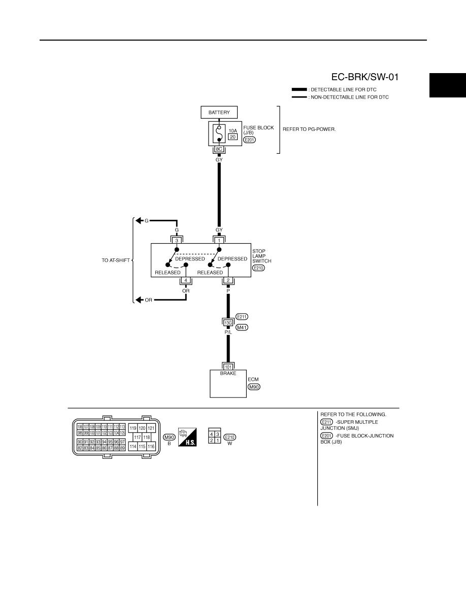
Wiring Diagram
INFOID:0000000001326360
Specification data are reference values and are measured between each terminal and ground.
CAUTION:
Do not use ECM ground terminals when measuring input/output voltage. Doing so may result in dam-
age to the ECM's transistor. Use a ground other than ECM terminals, such as the ground.
TBWM1403E
EC-488
< SERVICE INFORMATION >
[VQ35DE]
DTC P1805 BRAKE SWITCH
Diagnosis Procedure
INFOID:0000000001326361
1.
CHECK STOP LAMP SWITCH CIRCUIT
1.
Turn ignition switch OFF.
2.
Check the stop lamp when depressing and releasing the brake pedal.
OK or NG
OK
>> GO TO 4.
NG
>> GO TO 2.
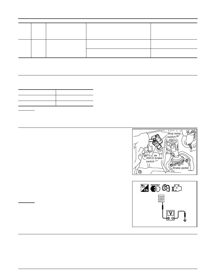
2.
CHECK STOP LAMP SWITCH POWER SUPPLY CIRCUIT
1.
Disconnect stop lamp switch harness connector.
2.
Check voltage between stop lamp switch terminal 1 and ground
with CONSULT-III or tester.
OK or NG
OK
>> GO TO 4.
NG
>> GO TO 3.
3.
DETECT MALFUNCTIONING PART
Check the following.
• 10A fuse
• Fuse block (J/B) connector E201
• Harness for open and short between stop lamp switch and battery
>> Repair open circuit or short to ground or short to power in harness or connectors.
4.
CHECK STOP LAMP SWITCH INPUT SIGNAL CIRCUIT FOR OPEN AND SHORT
TER-
MI-
NAL
NO.
WIRE
COLOR
ITEM
CONDITION
DATA (DC Voltage)
101
P/L
Stop lamp switch
[Ignition switch: OFF]
• Brake pedal: Fully released
Approximately 0V
[Ignition switch: OFF]
• Brake pedal: Slightly depressed
BATTERY VOLTAGE
(11 - 14V)
Brake pedal
Stop lamp
Fully released
Not illuminated
Slightly depressed
Illuminated
PBIB1605E
Voltage: Battery voltage
PBIB1184E
Нет комментариевНе стесняйтесь поделиться с нами вашим ценным мнением.
Текст