Infiniti FX35 / FX45. Manual — part 52

AT-136
< SERVICE INFORMATION >
DTC P1710 A/T FLUID TEMPERATURE SENSOR CIRCUIT
2.
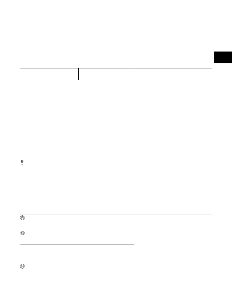
Check resistance between terminals.
3.
If NG, replace the A/T fluid temperature sensor 2. Refer to
215, "Control Valve with TCM and A/T Fluid Temperature Sen-
sor 2"
Name
Connector
Terminal
Temperature
°
C (
°
F)
Resistance (Ap-
prox.)
A/T fluid temperature
sensor 2
F507
1 - 2
0 (32)
10 k
Ω
20 (68)
4 k
Ω
80 (176)
0.5 k
Ω
SCIA5271E
DTC P1721 VEHICLE SPEED SENSOR MTR
AT-137
< SERVICE INFORMATION >
D
E
F
G
H
I
J
K
L
M
A
B
AT
N
O
P
DTC P1721 VEHICLE SPEED SENSOR MTR
Description
INFOID:0000000001327241
The vehicle speed sensor-MTR signal is transmitted from unified meter and A/C amp. to TCM by CAN com-
munication line. The signal functions as an auxiliary device to the revolution sensor when it is malfunctioning.
The TCM will then use the vehicle speed sensor·MTR signal.
CONSULT-III Reference Value in Data Monitor Mode
INFOID:0000000001327242
On Board Diagnosis Logic
INFOID:0000000001327243
Diagnostic trouble code “P1721 VEH SPD SE/CIR-MTR” with CONSULT-III is detected when TCM does not
receive the proper vehicle speed sensor MTR signal (input by CAN communication) from combination meter.
Possible Cause
INFOID:0000000001327244
Harness or connectors
(Sensor circuit is open or shorted.)
DTC Confirmation Procedure
INFOID:0000000001327245
CAUTION:
Always drive vehicle at a safe speed.
NOTE:
If “DTC Confirmation Procedure” has been previously performed, always turn ignition switch OFF and
wait at least 10 seconds before performing the next test.
After the repair, perform the following procedure to confirm the malfunction is eliminated.
WITH CONSULT-III
1.
Turn ignition switch ON.
2.
Select “ECU INPUT SIGNALS” in “DATA MONITOR” mode for “TRANSMISSION” with CONSULT-III.
3.
Touch “START”.
4.
Start engine and maintain the following conditions for at least 5 consecutive seconds.
ACCELE POSI: 1.0/8 or less
VHCL/S SE-MTR: 30 km/h (17 MPH) or more
5.
If DTC is detected, go to
Diagnosis Procedure
INFOID:0000000001327246
1.
CHECK CAN COMMUNICATION LINE
With CONSULT-III
• Perform the self-diagnosis.
Without CONSULT-III
• Perform the self-diagnosis. Refer to
AT-91, "Diagnosis Procedure without CONSULT-III"
.
Is malfunction in the CAN communication indicated in the result?
YES
>> Check CAN communication line. Refer to
NO
>> GO TO 2.
2.
CHECK INPUT SIGNAL
With CONSULT-III
1.
Start engine.
2.
Select “ECU INPUT SIGNALS” in “DATA MONITOR” mode for “TRANSMISSION” with CONSULT-III.
3.
Drive vehicle and read out the value of “VHCL/S SE-MTR”.
Item name
Condition
Display value
VHCL/S SE-MTR
During driving
Approximately matches the speedometer reading.

AT-138
< SERVICE INFORMATION >
DTC P1721 VEHICLE SPEED SENSOR MTR
OK or NG
OK
>> GO TO 4.
NG
>> GO TO 3.
3.
CHECK COMBINATION METERS
Check combination meters. Refer to
.
OK or NG
OK
>> GO TO 4.
NG
>> Repair or replace damaged parts.
4.
CHECK DTC
Perform
AT-137, "DTC Confirmation Procedure"
.
OK or NG
OK
>> INSPECTION END
NG
>> GO TO 5.
5.
CHECK TCM POWER SUPPLY AND GROUND CIRCUIT
Check TCM power supply and ground circuit. Refer to
OK or NG
OK
>> GO TO 6.
NG
>> Repair or replace damaged parts.
6.
DETECT MALFUNCTIONING ITEM
Check A/T assembly harness connector pin terminals for damage or loose connection with harness connector.
OK or NG
OK
>> Replace the control valve with TCM. Refer to
AT-215, "Control Valve with TCM and A/T Fluid Tem-
.
NG
>> Repair or replace damaged parts.
Item name
Condition
Display value
VHCL/S SE-MTR
During driving
Approximately matches the speedometer reading.

DTC P1730 A/T INTERLOCK
AT-139
< SERVICE INFORMATION >
D
E
F
G
H
I
J
K
L
M
A
B
AT
N
O
P
DTC P1730 A/T INTERLOCK
Description
INFOID:0000000001327247
Fail-safe function to detect interlock conditions.
On Board Diagnosis Logic
INFOID:0000000001327248
Diagnostic trouble code “P1730 A/T INTERLOCK” with CONSULT-III or 12th judgement flicker without CON-
SULT-III is detected when TCM does not receive the proper voltage signal from the sensor and switch.
TCM monitors and compares gear position and conditions of each ATF pressure switch when gear is steady.
Possible Cause
INFOID:0000000001327249
• Harness or connectors
(Solenoid and switch circuit is open or shorted.)
• Low coast brake solenoid valve
• ATF pressure switch 2
DTC Confirmation Procedure
INFOID:0000000001327250
NOTE:
If “DTC Confirmation Procedure” has been previously performed, always turn ignition switch OFF and
wait at least 10 seconds before performing the next test.
After the repair, perform the following procedure to confirm the malfunction is eliminated.
WITH CONSULT-III
1.
Turn ignition switch ON.
2.
Select “MAIN SIGNALS” in “DATA MONITOR” mode for “TRANSMISSION” with CONSULT-III.
3.
Touch “START”.
4.
Start engine.
5.
Drive vehicle and maintain the following conditions for at least 2 consecutive seconds.
SLCT LVR POSI: “D” position
6.
If DTC is detected, go to
WITH GST
Follow the procedure “WITH CONSULT-III”.
Judgement of A/T Interlock
INFOID:0000000001327251
• When A/T Interlock is judged to be malfunctioning, the vehicle should be fixed in 2nd gear, and should be set
in a condition in which it can travel.
When one of the following fastening patterns is detected, the fail-safe function in correspondence with the
individual pattern should be performed.
NOTE:
When the vehicle is driven fixed in 2nd gear, a turbine revolution sensor malfunction is displayed, but
this is not a turbine revolution sensor malfunction.
• When interlock is detected at the 3rd gear or more, it is locked at the 2nd gear.
Diagnosis Procedure
INFOID:0000000001327252
1.
SELF-DIAGNOSIS
With CONSULT-III
1.
Drive vehicle.
2.
Stop vehicle and turn ignition switch OFF.
3.
Turn ignition switch ON.
4.
Select “SELF-DIAG RESULTS” mode for “TRANSMISSION” with CONSULT-III.
Without CONSULT-III
1.
Drive vehicle.
2.
Stop vehicle and turn ignition switch OFF.
3.
Turn ignition switch ON.
Нет комментариевНе стесняйтесь поделиться с нами вашим ценным мнением.
Текст