Infiniti FX35 / FX45. Manual — part 53

AT-140
< SERVICE INFORMATION >
DTC P1730 A/T INTERLOCK
4.
Perform self-diagnosis. Refer to
AT-91, "Diagnosis Procedure without CONSULT-III"
.
OK or NG
OK
>> GO TO 2.
NG
>> Check low coast brake solenoid valve circuit and function. Refer to
2.
CHECK DTC
Perform
AT-139, "DTC Confirmation Procedure"
.
OK or NG
OK
>> INSPECTION END
NG
>> GO TO 3.
3.
CHECK TCM POWER SUPPLY AND GROUND CIRCUIT
Check TCM power supply and ground circuit. Refer to
OK or NG
OK
>> GO TO 4.
NG
>> Repair or replace damaged parts.
4.
DETECT MALFUNCTIONING ITEM
Check A/T assembly harness connector pin terminals for damage or loose connection with harness connector.
OK or NG
OK
>> Replace the control valve with TCM. Refer to
AT-215, "Control Valve with TCM and A/T Fluid Tem-
.
NG
>> Repair or replace damaged parts.
DTC P1731 A/T 1ST ENGINE BRAKING
AT-141
< SERVICE INFORMATION >
D
E
F
G
H
I
J
K
L
M
A
B
AT
N
O
P
DTC P1731 A/T 1ST ENGINE BRAKING
Description
INFOID:0000000001327253
Fail-safe function to prevent sudden decrease in speed by engine brake other than at M1 position.
CONSULT-III Reference Value in Data Monitor Mode
INFOID:0000000001327254
On Board Diagnosis Logic
INFOID:0000000001327255
Diagnostic trouble code “P1731 A/T 1ST E/BRAKING” with CONSULT-III or 13th judgement flicker without
CONSULT-III is detected under the following conditions.
• When TCM does not receive the proper voltage signal from the sensor.
• When TCM monitors each ATF pressure switch and solenoid monitor value, and detects as irregular when
engine brake of 1st gear acts other than at M1 position.
Possible Cause
INFOID:0000000001327256
• Harness or connectors
(Sensor circuit is open or shorted.)
• Low coast brake solenoid valve
• ATF pressure switch 2
DTC Confirmation Procedure
INFOID:0000000001327257
CAUTION:
• Always drive vehicle at a safe speed.
• Be careful not to rev engine into red zone on the tachometer.
NOTE:
If “DTC Confirmation Procedure” has been previously preformed, always turn ignition switch OFF and
wait at least 10 seconds before performing the next test.
After the repair, perform the following procedure to confirm the malfunction is eliminated.
WITH CONSULT-III
1.
Turn ignition switch ON.
2.
Select “SELECTION FROM MENU” in “DATA MONITOR” mode for “TRANSMISSION” with CONSULT-III
and check monitor “ENGINE SPEED”, “MANU MODE SW” and “GEAR”.
3.
Touch “START”.
4.
Start engine.
5.
Drive vehicle and maintain the following conditions for at least 2 consecutive seconds.
ENGINE SPEED: 1,200 rpm
MANU MODE SW: ON
GEAR: “1” position
6.
If DTC is detected, go to
Diagnosis Procedure
INFOID:0000000001327258
1.
CHECK INPUT SIGNALS
With CONSULT-III
1.
Start the engine.
2.
Select “SELECTION FROM MENU” in “DATA MONITOR” mode for “TRANSMISSION” with CONSULT-III.
3.
Drive vehicle in the “M” position (1st gear), and confirm the ON/OFF actuation of “ATF PRES SW 2” and
“ON OFF SOL”.
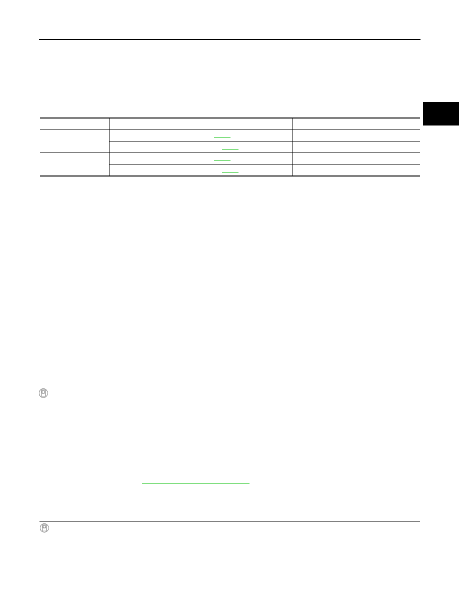
Item name
Condition
Display value
ON OFF SOL
Low coast brake engaged. Refer to
.
ON
Low coast brake disengaged. Refer to
.
OFF
ATF PRES SW 2
Low coast brake engaged. Refer to
.
ON
Low coast brake disengaged. Refer to
.
OFF

AT-142
< SERVICE INFORMATION >
DTC P1731 A/T 1ST ENGINE BRAKING
OK or NG
OK
>> GO TO 4.
NG
>> GO TO 2.
2.
CHECK TCM POWER SUPPLY AND GROUND CIRCUIT
Check TCM power supply and ground circuit. Refer to
OK or NG
OK
>> GO TO 3.
NG
>> Repair or replace damaged parts.
3.
DETECT MALFUNCTIONING ITEM
Check A/T assembly harness connector pin terminals for damage or loose connection with harness connector.
OK or NG
OK
>> Replace the control valve with TCM. Refer to
AT-215, "Control Valve with TCM and A/T Fluid Tem-
.
NG
>> Repair or replace damaged parts.
4.
CHECK DTC
Perform
AT-141, "DTC Confirmation Procedure"
.
OK or NG
OK
>> INSPECTION END
NG
>> GO TO 2.
Item name
Condition
Display value
ON OFF SOL
Low coast brake engaged. Refer to
ON
Low coast brake disengaged. Refer to
OFF
ATF PRES SW 2
Low coast brake engaged. Refer to
ON
Low coast brake disengaged. Refer to
OFF

DTC P1752 INPUT CLUTCH SOLENOID VALVE
AT-143
< SERVICE INFORMATION >
D
E
F
G
H
I
J
K
L
M
A
B
AT
N
O
P
DTC P1752 INPUT CLUTCH SOLENOID VALVE
Description
INFOID:0000000001327259
Input clutch solenoid valve is controlled by the TCM in response to signals sent from the PNP switch, vehicle
speed sensor and accelerator pedal position sensor (throttle position sensor). Gears will then be shifted to the
optimum position.
CONSULT-III Reference Value in Data Monitor Mode
INFOID:0000000001327260
On Board Diagnosis Logic
INFOID:0000000001327261
Diagnostic trouble code “P1752 I/C SOLENOID/CIRC” with CONSULT-III or 5th judgement flicker without
CONSULT-III is detected under the following conditions.
• When TCM detects an improper voltage drop when it tries to operate the solenoid valve.
• When TCM detects as irregular by comparing target value with monitor value.
Possible Cause
INFOID:0000000001327262
• Harness or connectors
(Solenoid circuit is open or shorted.)
• Input clutch solenoid valve
DTC Confirmation Procedure
INFOID:0000000001327263
CAUTION:
Always drive vehicle at a safe speed.
NOTE:
If “DTC Confirmation Procedure” has been previously performed, always turn ignition switch OFF and
wait at least 10 seconds before performing the next test.
After the repair, perform the following procedure to confirm the malfunction is eliminated.
WITH CONSULT-III
1.
Turn ignition switch ON.
2.
Select “SELECTION FROM MENU” in “DATA MONITOR” mode for “TRANSMISSION” with CONSULT-III
and check monitor “ACCELE POSI”, “SLCT LVR POSI” and “GEAR”.
3.
Touch “START”.
4.
Start engine.
5.
Drive vehicle and maintain the following conditions for at least 5 consecutive seconds.
ACCELE POSI: 1.5/8 - 2.0/8
SLCT LVR POSI: “D” position
GEAR: “3”
⇒
“4” (I/C ON/OFF)
Driving location: Driving the vehicle uphill (increased engine load) will help maintain the driving
conditions required for this test.
6.
If DTC is detected go to
.
WITH GST
Follow the procedure “WITH CONSULT-III”.
Diagnosis Procedure
INFOID:0000000001327264
1.
CHECK INPUT SIGNAL
With CONSULT-III
1.
Turn ignition switch ON.
2.
Select “MAIN SIGNALS” in “DATA MONITOR” mode for “TRANSMISSION” with CONSULT-III.
3.
Start the engine.
Item name
Condition
Display value (Approx.)
I/C SOLENOID
Input clutch disengaged. Refer to
0.6 - 0.8 A
Input clutch engaged. Refer to
0 - 0.05 A
Нет комментариевНе стесняйтесь поделиться с нами вашим ценным мнением.
Текст