Infiniti FX35 / FX45. Manual — part 79

AT-244
< SERVICE INFORMATION >
TRANSMISSION ASSEMBLY
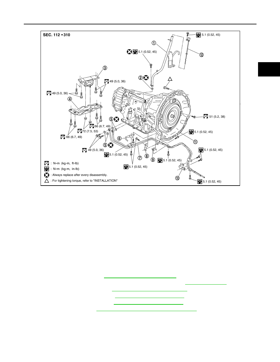
COMPONENTS (FOR VK45DE)
1.
A/T fluid charging pipe
2.
O-ring
3.
Engine mounting insulator (rear)
4.
Rear engine mounting member
5.
Copper washer
6.
Bracket
7.
Fluid cooler tube
8.
Bracket
9.
A/T assembly
10. A/T fluid level gauge
SCIA6425E
TRANSMISSION ASSEMBLY
AT-245
< SERVICE INFORMATION >
D
E
F
G
H
I
J
K
L
M
A
B
AT
N
O
P
REMOVAL
CAUTION:
• When removing the A/T assembly from engine, first remove the crankshaft position sensor (POS)
from the A/T assembly.
• Be careful not to damage sensor edge.
1.
Disconnect the battery cable from the negative terminal.
2.
Remove engine cover.
3.
Remove A/T fluid level gauge.
4.
Remove engine under cover with power tool.
5.
Remove front cross bar. Refer to
FSU-6, "Removal and Installation"
.
6.
Remove exhaust front tube and center muffler with power tool. Refer to
.
7.
Remove three way catalyst. Refer to
EM-179, "Removal and Installation"
8.
Remove front propeller shaft. Refer to
PR-4, "Removal and Installation"
.
9.
Remove rear propeller shaft. Refer to
PR-9, "Removal and Installation"
10. Remove control rod. Refer to
AT-206, "Control Rod Removal and Installation"
.
1.
A/T fluid charging pipe
2.
O-ring
3.
Engine mounting insulator (rear)
4.
Rear engine mounting member
5.
Copper washer
6.
Bracket
7.
Fluid cooler tube
8.
Bracket
9.
Bracket
10. Bracket
11.
A/T assembly
12. A/T fluid level gauge
SCIA6426E
AT-246
< SERVICE INFORMATION >
TRANSMISSION ASSEMBLY
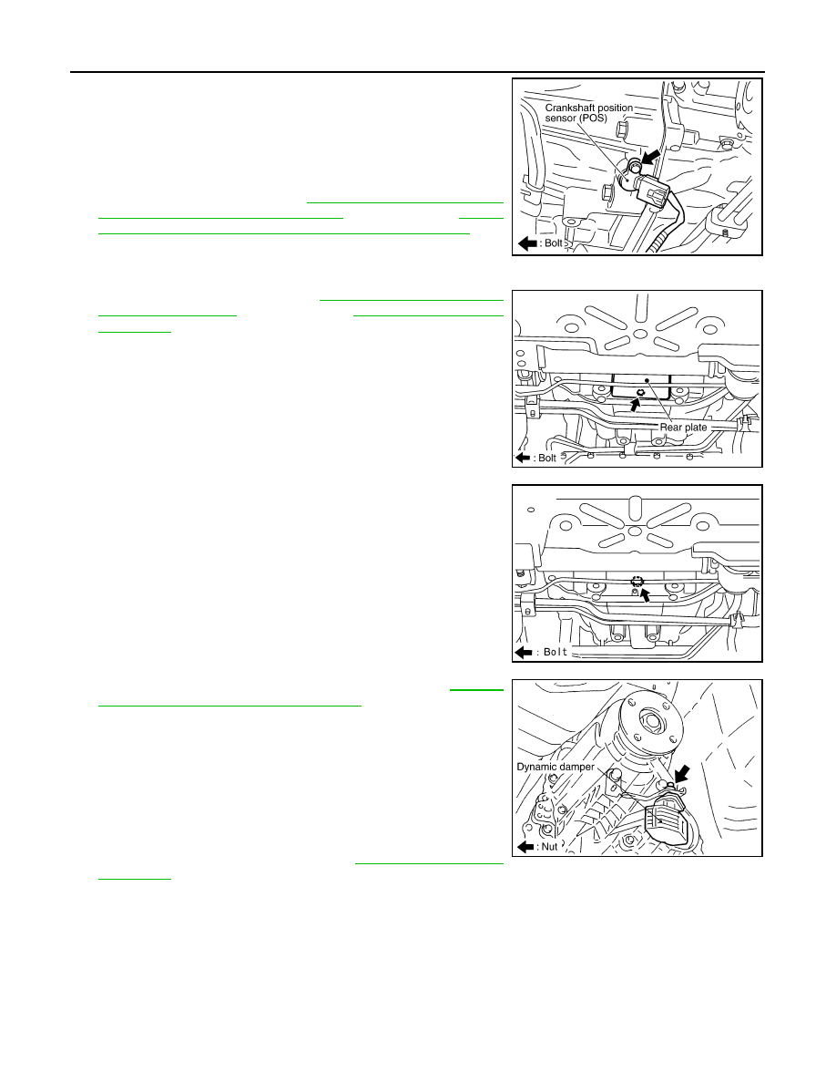
11. Remove crankshaft position sensor (POS) from A/T assembly.
CAUTION:
• Do not subject it to impact by dropping or hitting it.
• Do not disassemble.
• Do not allow metal filings, etc., to get on the sensor's front
edge magnetic area.
• Do not place in an area affected by magnetism.
12. Remove starter motor. Refer to
tion [VQ35DE Engine Models (AWD)]"
(for VQ35DE) or
"Removal and Installation (VK45DE Engine Models)"
(for
VK45DE).
13. Disconnect fluid cooler tube from A/T assembly.
14. Remove rear plate cover. Refer to
(for VK45DE).
15. Turn crankshaft, and remove the four tightening bolts for drive
plate and torque converter.
CAUTION:
When turning crankshaft, turn it clockwise as viewed from
the front of the engine.
16. Remove dynamic damper (for VQ35DE). Refer to
"Removal and Installation (AWD Models)"
17. Support A/T assembly with a transmission jack.
CAUTION:
When setting the transmission jack, be careful not to allow
it to collide against the drain plug.
18. Remove rear engine mounting member with power tool.
19. Remove engine mounting insulator (rear).
20. Tilt the A/T assembly slightly to keep the clearance between
body and A/T assembly, and then disconnect air breather hose
from A/T fluid charging pipe. Refer to
.
21. Disconnect A/T assembly harness connector and transfer assembly harness connector.
22. Remove A/T fluid charging pipe.
23. Remove O-ring from A/T fluid charging pipe.
24. Plug up openings such as the A/T fluid charging pipe hole, etc.
25. Remove bolts fixing transmission assembly to engine with power tool.
SCIA2011E
SCIA5326E
SCIA2010E
SCIA2202E
TRANSMISSION ASSEMBLY
AT-247
< SERVICE INFORMATION >
D
E
F
G
H
I
J
K
L
M
A
B
AT
N
O
P
26. Remove A/T assembly with transfer from vehicle.
• Secure torque converter to prevent it from dropping.
• Secure A/T assembly to a jack.
27. Remove transfer from A/T assembly. Refer to
INSPECTION
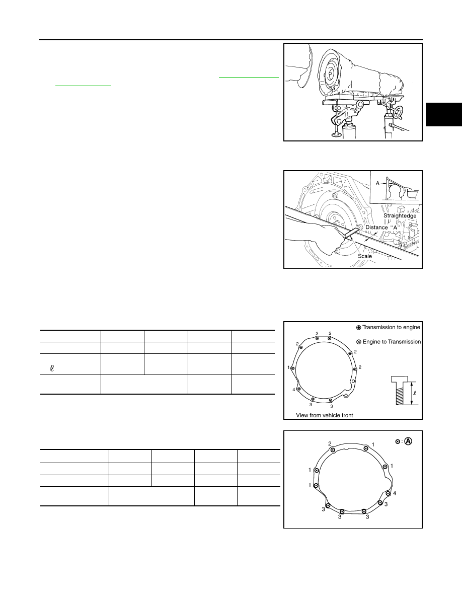
Installation and Inspection of Torque Converter
• After inserting a torque converter to a A/T, be sure to check dis-
tance “A” to ensure it is within the reference value limit.
INSTALLATION
Install the removed parts in the reverse order of the removal, while paying attention to the following work.
• When installing A/T assembly to the engine assembly, attach the fixing bolts in accordance with the following
standard.
For VQ35DE models
For VK45DE models
*1 : No.2 bolt also secures A/T fluid charging pipe and washer.
*2 : No.4 bolt also secures bracket.
(A) : A/T to engine
SCIA2203E
Distance “A”
VQ35DE models
: 25.0 mm (0.98 in) or more
VK45DE models
: 22.0 mm (0.87 in) or more
SAT017B
Bolt No.
1
2
3
4
Number of bolts
1
5
2
1
Bolt length
“
”mm (in)
55 (2.17)
65 (2.56)
35 (1.38)
40 (1.57)
Tightening torque
N·m (kg-m, ft-lb)
75
(7.7, 55)
47
(4.8, 35)
34
(3.5, 25)
SCIA4600E
Bolt No.
1
2
*1
3
4
*2
Number of bolts
4
1
4
1
Bolt length
mm (in)
70 (2.76)
70 (2.76)
65 (2.56)
70 (2.76)
Tightening torque
N·m (kg-m, ft-lb)
113
(12, 83)
74.0
(7.5, 55)
113
(12,83)
SCIA7756E
Нет комментариевНе стесняйтесь поделиться с нами вашим ценным мнением.
Текст