Infiniti FX35 / FX45. Manual — part 957
AIR BREATHER HOSE
TF-39
< SERVICE INFORMATION >
C
E
F
G
H
I
J
K
L
M
A
B
TF
N
O
P
AIR BREATHER HOSE
Removal and Installation
INFOID:0000000001327459
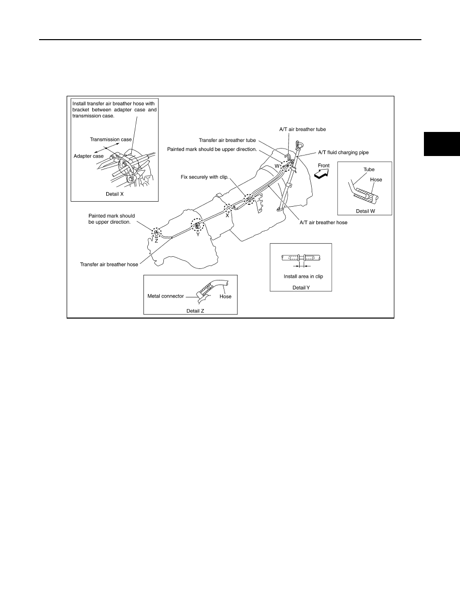
Refer to the figure for air breather hose removal and installation information.
CAUTION:
• Make sure there are no pinched or restricted areas on the air breather hose caused by bending or
winding when installing it.
• Be sure to insert air breather hose to transfer tube (metal connector) until hose end reaches the
tube's base and another hose end reaches the tube bend R portion of A/T fluid charging pipe.
SDIA2408E
TF-40
< SERVICE INFORMATION >
TRANSFER ASSEMBLY
TRANSFER ASSEMBLY
Removal and Installation
INFOID:0000000001327460
REMOVAL
1.
Remove tunnel stay with power tool. Refer to
RSU-6, "Removal and Installation"
.
2.
Remove exhaust front tube with power tool. Refer to
.
3.
Remove front and rear propeller shaft. Refer to
.
4.
Disconnect transfer assembly harness connector and separate harness from transfer assembly.
5.
Remove air breather hose. Refer to
.
6.
Support transfer assembly and transmission assembly with a jack.
7.
Remove engine rear member with power tool. Refer to
(VQ35DE) or
(VK45DE).
8.
Remove transfer mounting bolts and separate transfer from transmission.
CAUTION:
Secure transfer assembly to a jack.
INSTALLATION
Note the following, and install in the reverse order of removal.
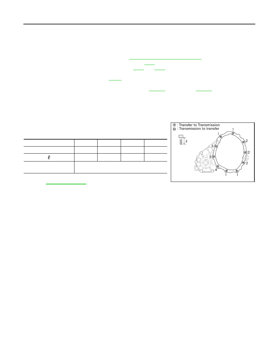
• When installing the transfer to the transmission, install the mount-
ing bolts following the standard below.
• After the installation, check the fluid level and for fluid leakage.
.
Disassembly and Assembly
INFOID:0000000001327461
COMPONENTS
Bolt No.
1
2
3
4
Quantity
4
3
2
1
Bolt length “
” mm (in)
75 (2.95)
45 (1.77)
40 (1.57)
30 (1.18)
Tightening torque
N·m (kg-m, ft-lb)
37 (3.8, 27)
SDIA2284E
TRANSFER ASSEMBLY
TF-41
< SERVICE INFORMATION >
C
E
F
G
H
I
J
K
L
M
A
B
TF
N
O
P
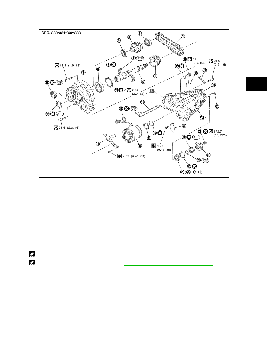
DISASSEMBLY
Front Case and Rear Case
1.
Remove drain plug and filler plug.
1.
Drive chain
2.
Front drive shaft rear bearing
3.
Front drive shaft
4.
Front drive shaft front bearing
5.
Sprocket
6.
Mainshaft
7.
Needle bearing
8.
Snap ring
9.
Mainshaft bearing
10. Front case
11.
Front oil seal
12. Mainshaft oil seal
13. Oil cover
14. Electric controlled coupling
15. Spacer
16. Snap ring
17. O-ring
18. Oil gutter
19. Drain plug
20. Baffle plate
21. Rear bearing
22. Snap ring
23. Spacer
24. Rear oil seal
25. Companion flange
26. Self-lock nut
27. Breather tube
28. Rear case
29. Harness bracket
30. Retainer
31. Filler plug
32. Gasket
1: Apply Genuine Anaerobic Liquid Gasket or equivalent. Refer to
GI-44, "Recommended Chemical Product and Sealant"
.
2: Apply Genuine Silicone RTV or equivalent. Refer to
GI-44, "Recommended Chemical Product and Sealant"
Refer to
for symbols not described on the above.
SDIA3608E
TF-42
< SERVICE INFORMATION >
TRANSFER ASSEMBLY
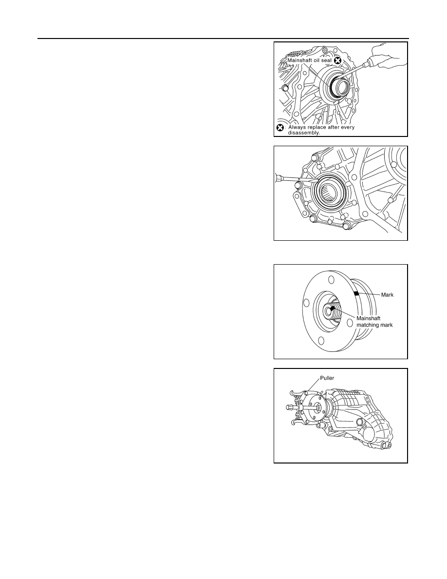
2.
Remove mainshaft oil seal from front case, using a flat-bladed
screwdriver.
CAUTION:
Be careful not to damage the front case and mainshaft.
3.
Remove front oil seal from front case, using a flat-bladed screw-
driver.
CAUTION:
Be careful not to damage the front case and front drive
shaft.
4.
Remove self-lock nut.
5.
Put a matching mark on the end of mainshaft. The mark should
be in line with the mark on the companion flange.
CAUTION:
For matching mark, use paint. Do not damage mainshaft.
6.
Remove companion flange, using a puller.
CAUTION:
Be careful not to damage the companion flange.
PDIA0253E
PDIA0255E
SDIA2378E
PDIA0258E
Нет комментариевНе стесняйтесь поделиться с нами вашим ценным мнением.
Текст