Infiniti FX35 / FX45. Manual — part 435
DTC P2118 THROTTLE CONTROL MOTOR
EC-501
< SERVICE INFORMATION >
[VQ35DE]
C
D
E
F
G
H
I
J
K
L
M
A
EC
N
P
O
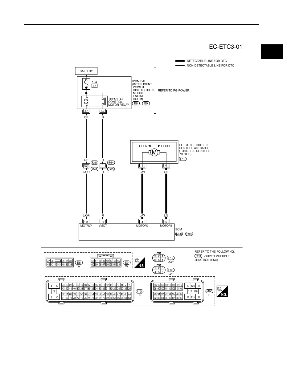
Wiring Diagram
INFOID:0000000001326379
Specification data are reference values and are measured between each terminal and ground.
Pulse signal is measured by CONSULT-III.
CAUTION:
TBWM1398E
EC-502
< SERVICE INFORMATION >
[VQ35DE]
DTC P2118 THROTTLE CONTROL MOTOR
Do not use ECM ground terminals when measuring input/output voltage. Doing so may result in dam-
age to the ECM's transistor. Use a ground other than ECM terminals, such as the ground.
: Average voltage for pulse signal (Actual pulse signal can be confirmed by oscilloscope.)
Diagnosis Procedure
INFOID:0000000001326380
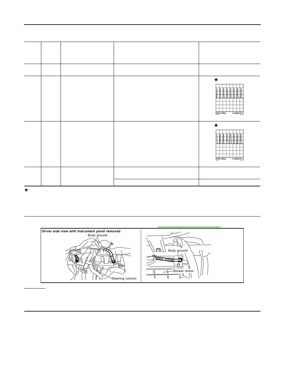
1.
CHECK GROUND CONNECTIONS
1.
Turn ignition switch OFF.
2.
Loosen and retighten ground screw on the body. Refer to
OK or NG
OK
>> GO TO 2.
NG
>> Repair or replace ground connections.
2.
CHECK THROTTLE CONTROL MOTOR OUTPUT SIGNAL CIRCUIT FOR OPEN OR SHORT
TER-
MI-
NAL
NO.
WIRE
COLOR
ITEM
CONDITION
DATA (DC Voltage)
3
R
Throttle control motor relay
power supply
[Ignition switch: ON]
BATTERY VOLTAGE
(11 - 14V)
4
L/W
Throttle control motor
(Close)
[Ignition switch: ON]
• Engine stopped
• Selector lever: D
• Accelerator pedal: Fully released
0 - 14V
5
L/B
Throttle control motor
(Open)
[Ignition switch: ON]
• Engine stopped
• Selector lever: D
• Accelerator pedal: Fully depressed
0 - 14V
104
L/OR
Throttle control motor relay
[Ignition switch: OFF]
BATTERY VOLTAGE
(11 - 14V)
[Ignition switch: ON]
0 - 1.0V
PBIB1104E
PBIB1105E
PBIB2625E
DTC P2118 THROTTLE CONTROL MOTOR
EC-503
< SERVICE INFORMATION >
[VQ35DE]
C
D
E
F
G
H
I
J
K
L
M
A
EC
N
P
O
1.
Disconnect electric throttle control actuator harness connector.
2.
Disconnect ECM harness connector.
3.
Check harness continuity between the following terminals.
Refer to Wiring Diagram.
4.
Also check harness for short to ground and short to power.
OK or NG
OK
>> GO TO 3.
NG
>> Repair or replace.
3.
CHECK THROTTLE CONTROL MOTOR
EC-503, "Component Inspection"
OK or NG
OK
>> GO TO 4.
NG
>> GO TO 5.
4.
CHECK INTERMITTENT INCIDENT
OK or NG
OK
>> GO TO 5.
NG
>> Repair or replace harness or connectors.
5.
REPLACE ELECTRIC THROTTLE CONTROL ACTUATOR
1.
Replace the electric throttle control actuator.
2.
EC-85, "Throttle Valve Closed Position Learning"
.
3.
EC-85, "Idle Air Volume Learning"
>> INSPECTION END
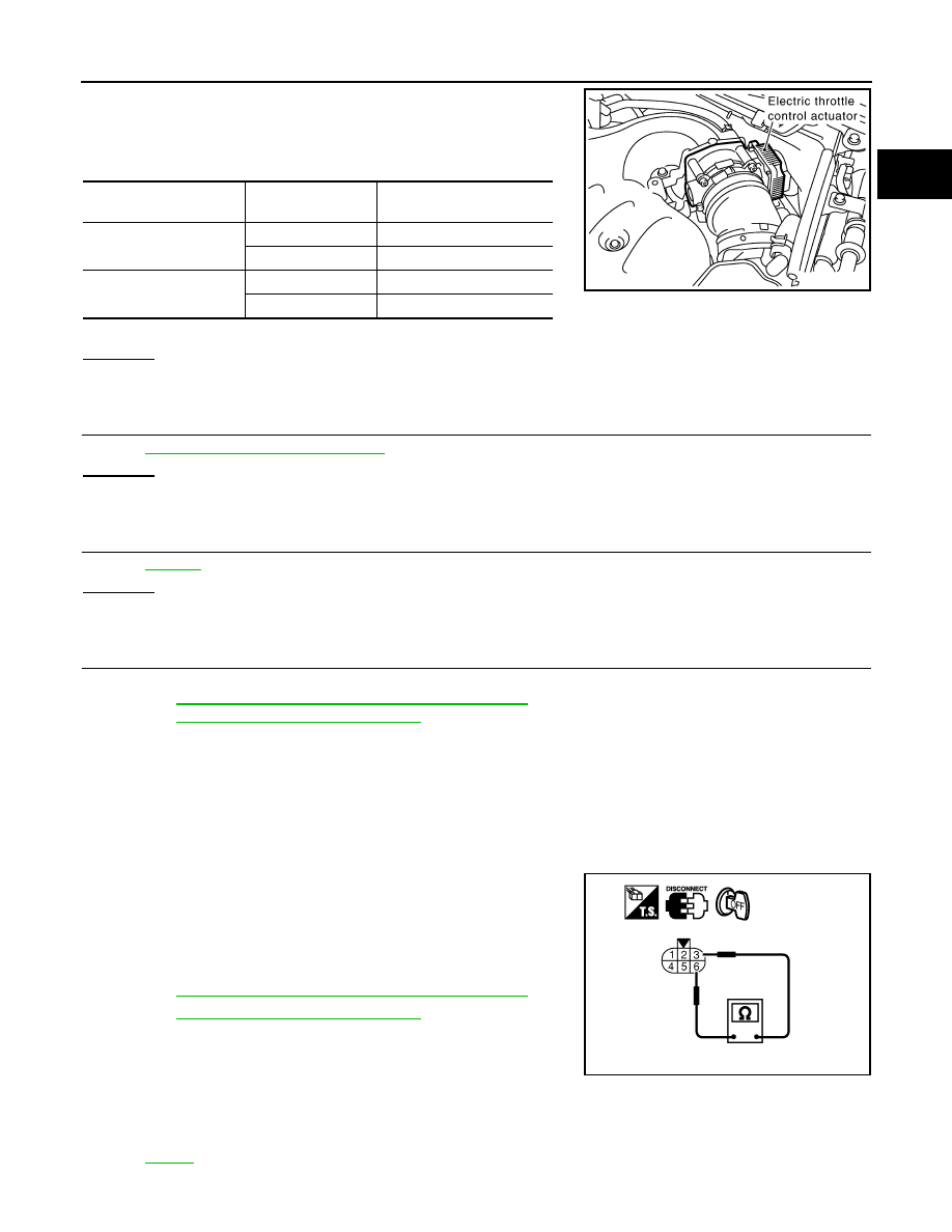
Component Inspection
INFOID:0000000001326381
THROTTLE CONTROL MOTOR
1.
Disconnect electric throttle control actuator harness connector.
2.
Check resistance between terminals 3 and 6.
3.
If NG, replace electric throttle control actuator and go to next
step.
4.
EC-85, "Throttle Valve Closed Position Learning"
.
5.
EC-85, "Idle Air Volume Learning"
Removal and Installation
INFOID:0000000001326382
ELECTRIC THROTTLE CONTROL ACTUATOR
Electric throttle control
actuator terminal
ECM terminal
Continuity
3
5
Should not exist
4
Should exist
6
5
Should exist
4
Should not exist
PBIB1557E
Resistance: Approximately 1 - 15
Ω
[at 25
°
C (77
°
F)]
PBIB0095E

EC-504
< SERVICE INFORMATION >
[VQ35DE]
DTC P2119 ELECTRIC THROTTLE CONTROL ACTUATOR
DTC P2119 ELECTRIC THROTTLE CONTROL ACTUATOR
Component Description
INFOID:0000000001326383
Electric throttle control actuator consists of throttle control motor, throttle position sensor, etc.
The throttle control motor is operated by the ECM and it opens and closes the throttle valve.
The throttle position sensor detects the throttle valve position, and the opening and closing speed of the throt-
tle valve and feeds the voltage signals to the ECM. The ECM judges the current opening angle of the throttle
valve from these signals and the ECM controls the throttle control motor to make the throttle valve opening
angle properly in response to driving condition.
On Board Diagnosis Logic
INFOID:0000000001326384
This self-diagnosis has the one trip detection logic.
FAIL-SAFE MODE
When the malfunction is detected, the ECM enters fail-safe mode and the MIL lights up.
DTC Confirmation Procedure
INFOID:0000000001326385
NOTE:
• Perform PROCEDURE FOR MALFUNCTION A AND B first. If the DTC cannot be confirmed, perform
PROCEDURE FOR MALFUNCTION C.
• If DTC Confirmation Procedure has been previously conducted, always turn ignition switch OFF and wait at
least 10 seconds before conducting the next test.
PROCEDURE FOR MALFUNCTION A AND B
1.
Turn ignition switch ON and wait at least 1 second.
2.
Shift selector lever to D position and wait at least 3 seconds.
3.
Shift selector lever to P, N position.
4.
Turn ignition switch OFF and wait at least 10 seconds.
5.
Turn ignition switch ON and wait at least 1 second.
6.
Shift selector lever to D position and wait at least 3 seconds.
7.
Shift selector lever to P, N position.
8.
Turn ignition switch OFF, wait at least 10 seconds and then turn ON.
9.
Check DTC.
10. If DTC is detected, go to
.
PROCEDURE FOR MALFUNCTION C
1.
Turn ignition switch ON and wait at least 1 second.
2.
Shift selector lever to D position and wait at least 3 seconds.
DTC No.
Trouble diagnosis name
DTC detecting condition
Possible cause
P2119
2119
Electric throttle control
actuator
A)
Electric throttle control actuator does not func-
tion properly due to the return spring malfunc-
tion.
• Electric throttle control actuator
B)
Throttle valve opening angle in fail-safe mode is
not in specified range.
C)
ECM detect the throttle valve is stuck open.
Detected items
Engine operating condition in fail-safe mode
Malfunction A
The ECM controls the electric throttle actuator by regulating the throttle opening around the idle position.
The engine speed will not rise more than 2,000 rpm.
Malfunction B
ECM controls the electric throttle control actuator by regulating the throttle opening to 20 degrees or less.
Malfunction C
While the vehicle is driving, it slows down gradually by fuel cut. After the vehicle stops, the engine stalls.
The engine can restart in N or P position, and engine speed will not exceed 1,000 rpm or more.
Нет комментариевНе стесняйтесь поделиться с нами вашим ценным мнением.
Текст