Infiniti FX35 / FX45. Manual — part 126

ATC-100
< SERVICE INFORMATION >
IN-VEHICLE SENSOR
IN-VEHICLE SENSOR
Removal and Installation
INFOID:0000000001328203
REMOVAL
1.
Remove instrument driver lower panel. Refer to
2.
Remove mounting screw, and then remove in-vehicle sensor.
INSTALLATION
Installation is basically the reverse order of removal.
RJIA2036E
SUNLOAD SENSOR
ATC-101
< SERVICE INFORMATION >
C
D
E
F
G
H
I
K
L
M
A
B
ATC
N
O
P
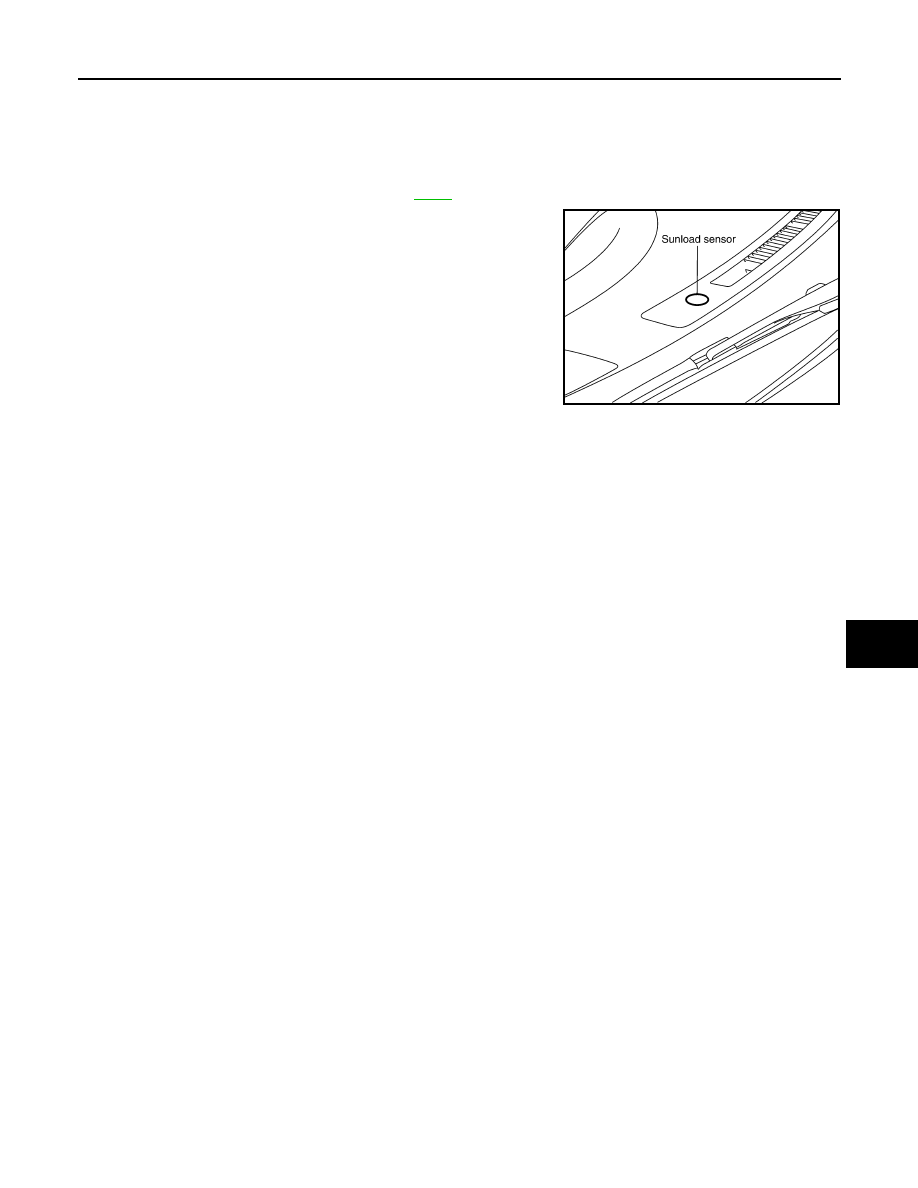
SUNLOAD SENSOR
Removal and Installation
INFOID:0000000001328204
REMOVAL
1.
Remove front defroster grille (RH). Refer to
2.
Disconnect sunload sensor connector, and then remove the
sunload sensor.
INSTALLATION
Installation is basically the reverse order of removal.
RJIA2026E
ATC-102
< SERVICE INFORMATION >
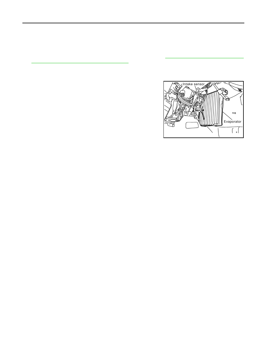
INTAKE SENSOR
INTAKE SENSOR
Removal and Installation
INFOID:0000000001328205
REMOVAL
1.
Remove low-pressure pipe 2 and high-pressure pipe 3. Refer to
ATC-133, "Removal and Installation of
Low-Pressure Pipe 2 and High-pressure Pipe 3"
CAUTION:
Cap or wrap the joint of evaporator, low-pressure pipe 1 and high-pressure pipe 2 with suitable
material such as vinyl tape to avoid the entry of air.
2.
Slide evaporator to passenger side, and then remove intake
sensor.
INSTALLATION
Installation is basically the reverse order of removal.
CAUTION:
• Replace O-rings of low-pressure pipe 1, 2 and high-pressure pipe 2, 3 with new ones, and then apply
compressor oil to it when installing it.
• Mark the mounting position of intake sensor bracket prior to removal so that the reinstalled sensor
can be located in the same position.
• Female-side piping connection is thin and easy to deform. Slowly insert the male-side piping
straight in axial direction.
• Insert piping securely until a click is heard.
• After piping connection is completed, pull male-side piping by hand to make sure that connection
does not come loose.
• When recharging refrigerant, check for leaks.
RJIA0928E

BLOWER UNIT
ATC-103
< SERVICE INFORMATION >
C
D
E
F
G
H
I
K
L
M
A
B
ATC
N
O
P
BLOWER UNIT
Removal and Installation
INFOID:0000000001328206
REMOVAL
1.
Remove instrument passenger lower panel. Refer to
.
2.
Remove mounting nut, and then remove ECM with bracket
attached.
3.
Disconnect intake door motor connector and blower fan motor
connector.
4.
Remove harness clip from blower unit.
5.
Remove mounting bolt and screws from blower unit.
CAUTION:
Move blower unit rightward, and remove locating pin (1
part) and joint. Then remove blower unit downward.
6.
Remove blower unit.
INSTALLATION
Installation is basically the reverse order of removal.
CAUTION:
Make sure locating pin (1 part) and joint are securely inserted.
RJIA2039E
RJIA0943E
Нет комментариевНе стесняйтесь поделиться с нами вашим ценным мнением.
Текст