Infiniti FX35 / FX45. Manual — part 124
ATC-92
< SERVICE INFORMATION >
TROUBLE DIAGNOSIS
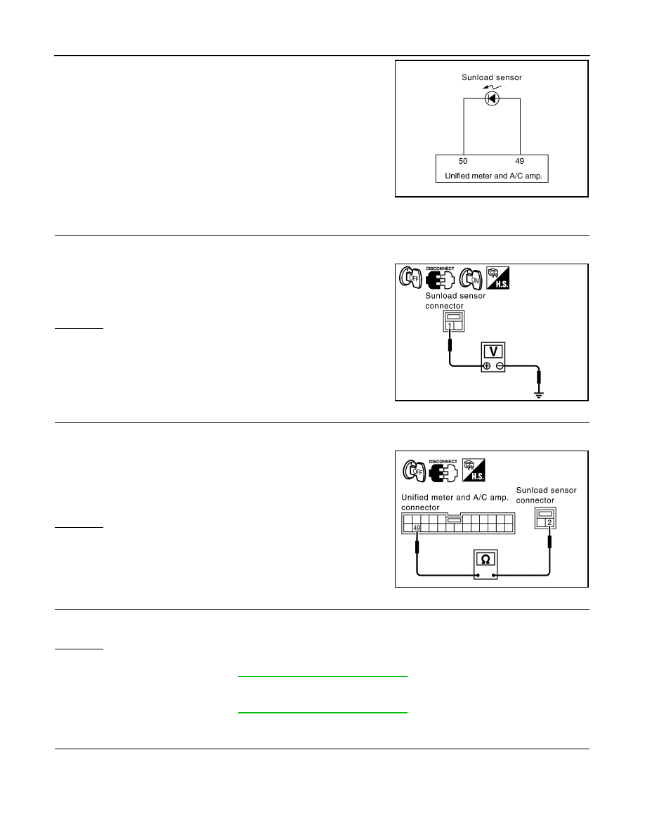
SYMPTOM: Sunload sensor circuit is open or shorted. (25 or
−
25 is
indicated on unified meter and A/C amp. as a result of performing
self-diagnosis STEP-2.)
1.
CHECK VOLTAGE BETWEEN SUNLOAD SENSOR AND GROUND
1.
Disconnect sunload sensor connector.
2.
Turn ignition switch ON.
3.
Check voltage between sunload sensor harness connector M87
terminal 1 and ground.
OK or NG
OK
>> GO TO 2.
NG
>> GO TO 4.
2.
CHECK CIRCUIT CONTINUITY BETWEEN SUNLOAD SENSOR AND UNIFIED METER AND A/C AMP.
1.
Turn ignition switch OFF.
2.
Disconnect unified meter and A/C amp. connector.
3.
Check continuity between sunload sensor harness connector
M87 terminal 2 and unified meter and A/C amp. harness con-
nector M57 terminal 49.
OK or NG
OK
>> GO TO 3.
NG
>> Repair harness or connector.
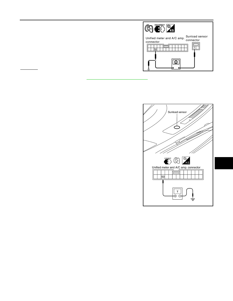
3.
CHECK SUNLOAD SENSOR
1.
Reconnect sunload sensor connector and unified meter and A/C amp. connector.
2.
Refer to "Sunload Sensor".
OK or NG
OK
>> 1.
Replace unified meter and A/C amp.
2.
ATC-43, "Self-Diagnosis Function"
and perform self-diagnosis STEP-2.
Confirm that code No. 20 is displayed.
NG
>> 1.
Replace sunload sensor.
2.
ATC-43, "Self-Diagnosis Function"
and perform self-diagnosis STEP-2.
Confirm that code No. 20 is displayed.
4.
CHECK CIRCUIT CONTINUITY BETWEEN SUNLOAD SENSOR AND UNIFIED METER AND A/C AMP.
1.
Turn ignition switch OFF.
2.
Disconnect unified meter and A/C amp. connector.
RJIA1455E
1 – Ground
: Approx. 5 V
RJIA2027E
2 – 49
: Continuity should exist.
RJIA2028E
TROUBLE DIAGNOSIS
ATC-93
< SERVICE INFORMATION >
C
D
E
F
G
H
I
K
L
M
A
B
ATC
N
O
P
3.
Check continuity between sunload sensor harness connector
M87 terminal 1 and unified meter and A/C amp. harness con-
nector M57 terminal 50.
4.
Check continuity between sunload sensor harness connector
M87 terminal 1 and ground.
OK or NG
OK
>> 1.
Replace unified meter and A/C amp.
2.
ATC-43, "Self-Diagnosis Function"
and perform self-diagnosis STEP-2.
Confirm that code No. 20 is displayed.
NG
>> Repair harness or connector.
COMPONENT INSPECTION
Sunload Sensor
Measure voltage between unified meter and A/C amp. harness con-
nector M57 terminal 50 and ground.
1 – 50
: Continuity should exist.
1 – Ground
: Continuity should not exist.
RJIA2029E
RJIA2030E

ATC-94
< SERVICE INFORMATION >
TROUBLE DIAGNOSIS
• When checking sunload sensor, select a place where sunshine directly on it.
If NG, replace sunload sensor.
Intake Sensor Circuit
INFOID:0000000001328199
COMPONENT DESCRIPTION
Intake Sensor
The intake sensor is located on the heater & cooling unit assembly. It
converts temperature of air after it passes through the evaporator
into a resistance value which is then input to the unified meter and A/
C amp.
DIAGNOSIS PROCEDURE FOR INTAKE SENSOR
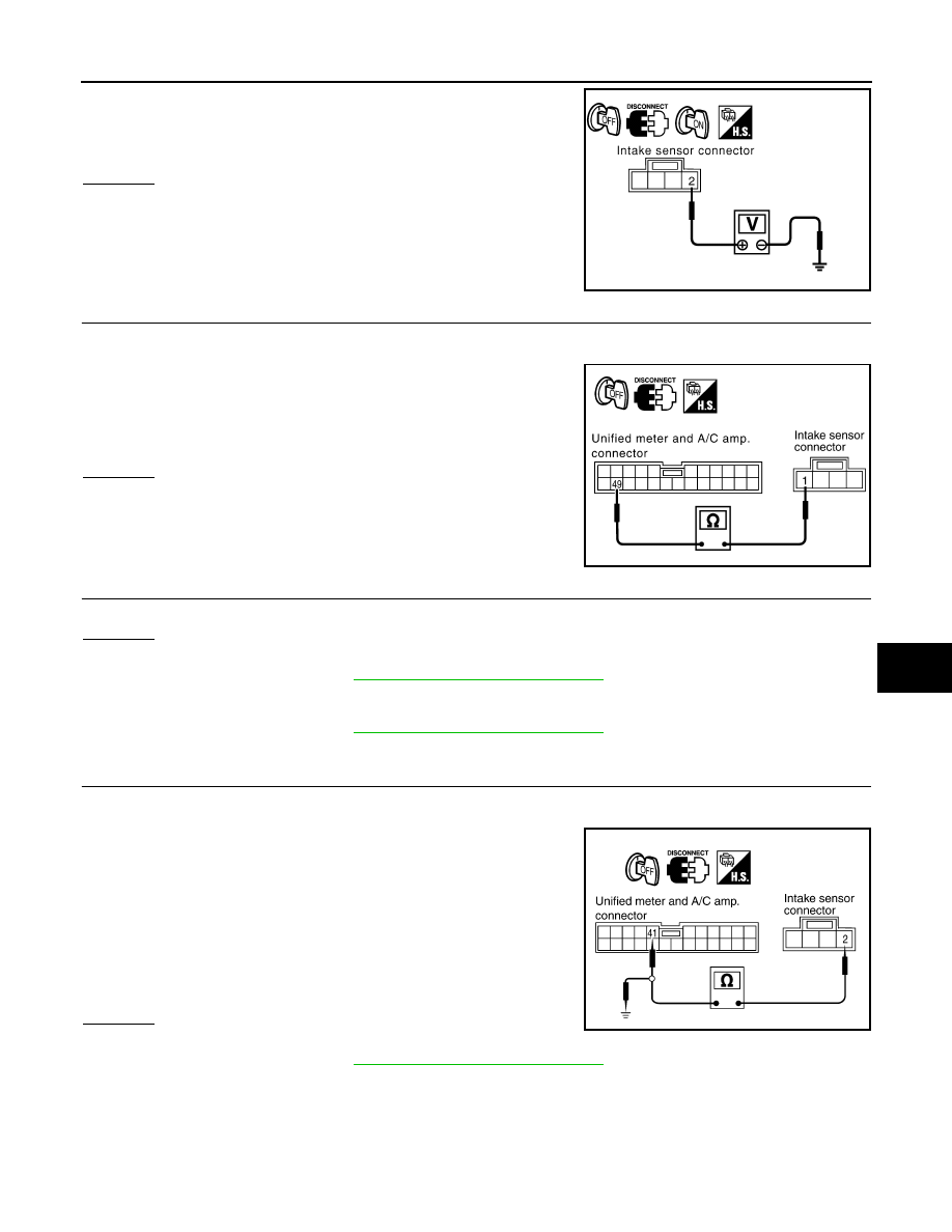
SYMPTOM: Intake sensor circuit is open or shorted. (24 or
−
24 is
indicated on unified meter and A/C amp. as a result of performing
self-diagnosis STEP-2.)
1.
CHECK VOLTAGE BETWEEN INTAKE SENSOR AND GROUND
1.
Disconnect intake sensor connector.
2.
Turn ignition switch ON.
SHA930E
RJIA0928E
RJIA1458E
TROUBLE DIAGNOSIS
ATC-95
< SERVICE INFORMATION >
C
D
E
F
G
H
I
K
L
M
A
B
ATC
N
O
P
3.
Check voltage between intake sensor harness connector M254
terminal 2 and ground.
OK or NG
OK
>> GO TO 2.
NG
>> GO TO 4.
2.
CHECK CIRCUIT CONTINUITY BETWEEN INTAKE SENSOR AND UNIFIED METER AND A/C AMP.
1.
Turn ignition switch OFF.
2.
Disconnect unified meter and A/C amp. connector.
3.
Check continuity between intake sensor harness connector
M254 terminal 1 and unified meter and A/C amp. harness con-
nector M57 terminal 49.
OK or NG
OK
>> GO TO 3.
NG
>> Repair harness or connector.
3.
CHECK INTAKE SENSOR
Refer to "Intake Sensor".
OK or NG
OK
>> 1.
Replace unified meter and A/C amp.
2.
ATC-43, "Self-Diagnosis Function"
and perform self-diagnosis STEP-2.
Confirm that code No. 20 is displayed.
NG
>> 1.
Replace intake sensor.
2.
ATC-43, "Self-Diagnosis Function"
and perform self-diagnosis STEP-2.
Confirm that code No. 20 is displayed.
4.
CHECK CIRCUIT CONTINUITY BETWEEN INTAKE SENSOR AND UNIFIED METER AND A/C AMP.
1.
Turn ignition switch OFF.
2.
Disconnect unified meter and A/C amp. connector.
3.
Check continuity between intake sensor harness connector
M254 terminal 2 and unified meter and A/C amp. harness con-
nector M57 terminal 41.
4.
Check continuity between intake sensor harness connector
M254 terminal 2 and ground.
OK or NG
OK
>> 1.
Replace unified meter and A/C amp.
2.
ATC-43, "Self-Diagnosis Function"
and perform self-diagnosis STEP-2.
Confirm that code No. 20 is displayed.
NG
>> Repair harness or connector.
COMPONENT INSPECTION
Intake Sensor
2 – Ground
: Approx. 5 V
RJIA2031E
1 – 49
: Continuity should exist.
RJIA2032E
2 – 41
: Continuity should exist.
2 – Ground
: Continuity should not exist.
RJIA2033E
Нет комментариевНе стесняйтесь поделиться с нами вашим ценным мнением.
Текст