Infiniti FX35 / FX45. Manual — part 718
PRECAUTIONS
GI-7
< SERVICE INFORMATION >
C
D
E
F
G
H
I
J
K
L
M
B
GI
N
O
P
• Heavily soiled clothing and oil-impregnated footwear should not be worn. Overalls must be cleaned regu-
larly.
• First aid treatment should be obtained immediately for open cuts and wounds.
• Use barrier creams, applying them before each work period, to help the removal of oil from the skin.
• Wash with soap and water to ensure all oil is removed (skin cleansers and nail brushes will help). Prepara-
tions containing lanolin replace the natural skin oils which have been removed.
• Do not use gasoline, kerosene, diesel fuel, gas oil, thinners or solvents for cleaning skin.
• If skin disorders develop, obtain medical advice without delay.
• Where practical, degrease components prior to handling.
• Where there is a risk of eye contact, eye protection should be worn, for example, chemical goggles or face
shields; in addition an eye wash facility should be provided.
Precaution for the Environment
INFOID:0000000001325661
In servicing the vehicle, it may be necessary to use, dispose of or recycle hazardous, flammable, or poisonous
materials, such as gasoline, refrigerant gas, solvents, oil, oil filter, air bag modules, seat belt pretensioners,
etc. Disposal, recycling, and transportation of any hazardous materials should be performed in compliance
with applicable federal, state and local laws and regulations.
Precaution for Air Conditioning
INFOID:0000000001325662
Use an approved refrigerant recovery unit any time the air conditioning system must be discharged. Refer to
ATC/MTC section “HFC-134a (R-134a) Service Procedure”, “REFRIGERANT LINES” for specific instructions.

GI-8
< SERVICE INFORMATION >
HOW TO USE THIS MANUAL
HOW TO USE THIS MANUAL
Description
INFOID:0000000001325663
This volume explains “Removal, Disassembly, Installation, Inspection and Adjustment” and “Trouble Diag-
noses”.
Terms
INFOID:0000000001325664
• The captions WARNING and CAUTION warn you of steps that must be followed to prevent personal injury
and/or damage to some part of the vehicle.
WARNING indicates the possibility of personal injury if instructions are not followed.
CAUTION indicates the possibility of component damage if instructions are not followed.
BOLD TYPED STATEMENTS except WARNING and CAUTION give you helpful information.
Standard value:Tolerance at inspection and adjustment.
Limit value:The maximum or minimum limit value that should not be exceeded at inspection and adjustment.
Units
INFOID:0000000001325665
• The UNITS given in this manual are primarily expressed as the SI UNIT (International System of Unit), and
alternatively expressed in the metric system and in the yard/pound system.
Also with regard to tightening torque of bolts and nuts, there are descriptions both about range and about the
standard tightening torque.
“Example”
Range
Standard
Contents
INFOID:0000000001325666
• ALPHABETICAL INDEX is provided at the end of this manual so that you can rapidly find the item and page
you are searching for.
• A QUICK REFERENCE INDEX, a black tab (e.g.
) is provided on the first page. You can quickly find the
first page of each section by matching it to the section's black tab.
• THE CONTENTS are listed on the first page of each section.
• THE TITLE is indicated on the upper portion of each page and shows the part or system.
• THE PAGE NUMBER of each section consists of two or three letters which designate the particular section
and a number (e.g. “BR-5”).
• THE SMALL ILLUSTRATIONS show the important steps such as inspection, use of special tools, knacks of
work and hidden or tricky steps which are not shown in the previous large illustrations.
Assembly, inspection and adjustment procedures for the complicated units such as the automatic transaxle
or transmission, etc. are presented in a step-by-step format where necessary.
Component
INFOID:0000000001325667
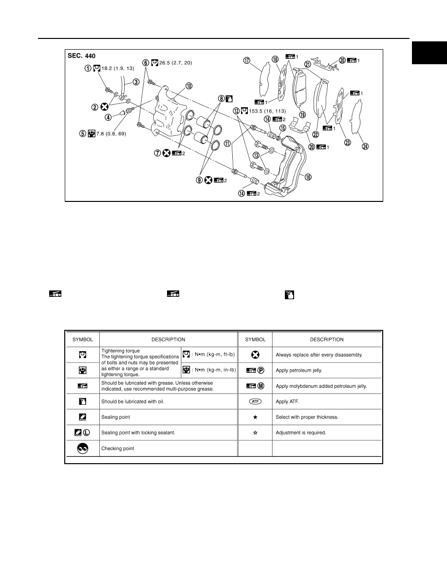
• THE LARGE ILLUSTRATIONS are exploded views (see the following) and contain tightening torques, lubri-
cation points, section number of the PARTS CATALOG (e.g. SEC. 440) and other information necessary to
perform repairs.
The illustrations should be used in reference to service matters only. When ordering parts, refer to the appro-
priate PARTS CATALOG.
Components shown in an illustration may be identified by a circled number. When this style of illustration is
used, the text description of the components will follow the illustration.
Outer Socket Lock Nut
: 59 - 78 N·m (6.0 - 8.0 kg-m, 43 - 58 ft-lb)
Drive Shaft Installation Bolt
: 44.3 N·m (4.5 kg-m, 33 ft-lb)
HOW TO USE THIS MANUAL
GI-9
< SERVICE INFORMATION >
C
D
E
F
G
H
I
J
K
L
M
B
GI
N
O
P
SYMBOLS
How to Follow Trouble Diagnosis
INFOID:0000000001325668
DESCRIPTION
NOTICE:
Trouble diagnoses indicate work procedures required to diagnose problems effectively. Observe the following
instructions before diagnosing.
1.
Before performing trouble diagnoses, read the “Preliminary Check”, the “Symptom Chart” or the
“Work Flow”.
2.
After repairs, re-check that the problem has been completely eliminated.
1.
Union bolt
2.
Copper washer
3.
Brake hose
4.
Cap
5.
Bleed valve
6.
Sliding pin bolt
7.
Piston seal
8.
Piston
9.
Piston boot
10.
Cylinder body
11.
Sliding pin
12.
Torque member mounting bolt
13.
Washer
14.
Sliding pin boot
15.
Bushing
16.
Torque member
17.
Inner shim cover
18.
Inner shim
19.
Inner pad
20.
Pad retainer
21.
Pad wear sensor
22.
Outer pad
23.
Outer shim
24.
Outer shim cover
1: PBC (Poly Butyl Cuprysil) grease
or silicone-based grease
2: Rubber grease
: Brake fluid
Refer to GI section for additional symbol definitions.
SFIA2959E
SAIA0749E
GI-10
< SERVICE INFORMATION >
HOW TO USE THIS MANUAL
3.
Refer to Component Parts and Harness Connector Location for the Systems described in each
section for identification/location of components and harness connectors.
4.
Refer to the Circuit Diagram for quick pinpoint check.
If you need to check circuit continuity between harness connectors in more detail, such as when a
sub-harness is used, refer to Wiring Diagram in each individual section and Harness Layout in PG
section for identification of harness connectors.
5.
When checking circuit continuity, ignition switch should be OFF.
6.
Before checking voltage at connectors, check battery voltage.
7.
After accomplishing the Diagnostic Procedures and Electrical Components Inspection, make sure
that all harness connectors are reconnected as they were.
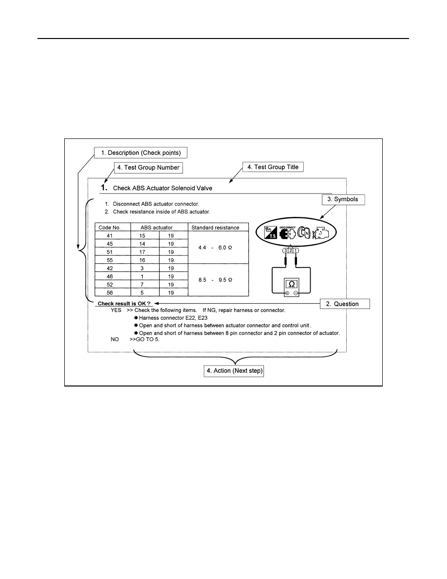
HOW TO FOLLOW TEST GROUPS IN TROUBLE DIAGNOSES
1.
Work and diagnostic procedure
Start to diagnose a problem using procedures indicated in enclosed test groups.
2.
Questions and required results
Questions and required results are indicated in bold type in test group.
The meaning of are as follows:
3.
Symbol used in illustration
Symbols included in illustrations refer to measurements or procedures. Before diagnosing a problem,
familiarize yourself with each symbol. Refer to "Connector Symbols" in GI Section and "KEY TO SYM-
BOLS SIGNIFYING MEASUREMENTS OR PROCEDURES" below.
4.
Action items
Next action for each test group is indicated based on result of each question. Test group number is shown
in the left upper portion of each test group.
HARNESS WIRE COLOR AND CONNECTOR NUMBER INDICATION
There are two types of harness wire color and connector number indication.
TYPE 1: Harness Wire Color and Connector Number are Shown in Illustration
SAIA0256E
a. Battery voltage
→
11 - 14V or approximately 12V
b. Voltage
: Approximately 0V
→
Less than 1V
Нет комментариевНе стесняйтесь поделиться с нами вашим ценным мнением.
Текст