Infiniti FX35 / FX45. Manual — part 627
INTAKE MANIFOLD
EM-25
< SERVICE INFORMATION >
[VQ35DE]
C
D
E
F
G
H
I
J
K
L
M
A
EM
N
P
O
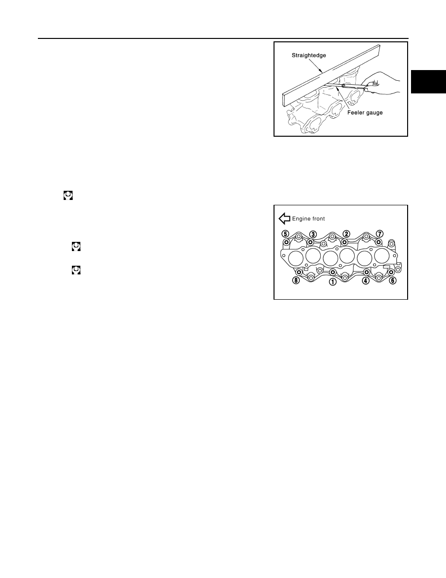
• Check the surface distortion of the intake manifold mating surface
with a straightedge and a feeler gauge.
• If it exceeds the limit, replace intake manifold.
INSTALLATION
Note the following, and install in the reverse order of removal.
Intake Manifold
• If stud bolts were removed, install them and tighten to the specified torque below.
• Tighten all mounting bolts and nuts to the specified torque in two or
more steps in numerical order shown in the figure.
Limit
: 0.1 mm (0.004 in)
PBIC0870E
: 10.8 N·m (1.1 kg-m, 8 ft-lb)
1st step:
: 7.4 N·m (0.75 kg-m, 5 ft-lb)
2nd step and after:
: 29.0 N·m (3.0 kg-m, 21 ft-lb)
PBIC0778E

EM-26
< SERVICE INFORMATION >
[VQ35DE]
EXHAUST MANIFOLD AND THREE WAY CATALYST
EXHAUST MANIFOLD AND THREE WAY CATALYST
Component
INFOID:0000000001325714
• Refer to
for symbols in the figure.
Removal and Installation
INFOID:0000000001325715
REMOVAL
WARNING:
Perform the work when the exhaust and cooling system have completely cooled down.
1.
Remove engine cover with power tool. Refer to
2.
Drain engine coolant. Refer to
CO-10, "Changing Engine Coolant"
.
CAUTION:
• Perform this step when the engine is cold.
• Do not spill engine coolant on drive belts.
3.
Remove air cleaner case and air duct. Refer to
.
4.
Remove front and rear engine undercover and front cross bar with power tool.
5.
Disconnect heated oxygen sensors 2 (bank 1 and bank 2) harness connectors.
1.
Heated oxygen sensor 2 (bank 1)
2.
Three way catalyst (right bank)
3.
Gasket
4.
Air fuel ratio sensor 1 (bank 1)
5.
Exhaust manifold cover (right bank)
6.
Exhaust manifold (right bank)
7.
Exhaust manifold (left bank)
8.
Exhaust manifold cover (left bank)
9.
Three way catalyst (left bank)
10. Air fuel ratio sensor 1 (bank 2)
11. Heated oxygen sensor 2 (bank 2)
JPBIA0829GB
EXHAUST MANIFOLD AND THREE WAY CATALYST
EM-27
< SERVICE INFORMATION >
[VQ35DE]
C
D
E
F
G
H
I
J
K
L
M
A
EM
N
P
O
6.
Using the heated oxygen sensor wrench (SST), remove heated
oxygen sensors 2 (bank 1 and bank 2).
CAUTION:
• Be careful not to damage heated oxygen sensor.
• Discard any heated oxygen sensor which has been
dropped onto a hard surface such as a concrete floor,
replace with a new sensor.
7.
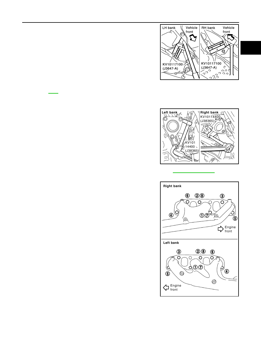
Remove exhaust mounting bracket between three way catalysts (right and left bank) and transmission.
Refer to
.
8.
Remove three way catalysts (right and left bank).
9.
Disconnect air fuel ratio sensor 1 (bank 1 and bank 2) harness connectors and remove harness clip.
10. Using the heated oxygen sensor wrench (SST), remove air fuel
ratio sensor 1 (bank 1 and bank 2).
CAUTION:
• Be careful not to damage air fuel ratio sensor.
• Discard any air fuel ratio sensor which has been dropped
onto a hard surface such as a concrete floor, replace with
a new sensor.
11. Remove water pipe and heater pipe on both right and left side. Refer to
.
12. Remove exhaust manifold cover (right and left bank).
13. Loosen mounting nuts in the reverse order as shown in the fig-
ure to remove exhaust manifold with power tool.
NOTE:
Disregard the numerical order No. 7 and 8 in removal.
14. Remove gaskets.
CAUTION:
Cover engine openings to avoid entry of foreign materials.
INSPECTION AFTER REMOVAL
KBIA1740E
SBIA0575E
PBIC2042E
EM-28
< SERVICE INFORMATION >
[VQ35DE]
EXHAUST MANIFOLD AND THREE WAY CATALYST
Surface Distortion
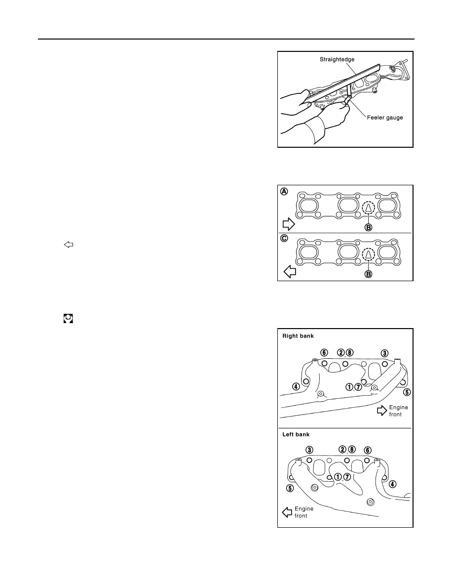
• Check the surface distortion of the exhaust manifold mating sur-
face with a straightedge and a feeler gauge.
• If it exceeds the limit, replace exhaust manifold.
INSTALLATION
Note the following, and install in the reverse order of removal.
Exhaust Manifold Gasket
• Install exhaust manifold gasket in direction shown in the figure.
(Follow same procedure for both banks.)
Exhaust Manifold
• If stud bolts were removed, install them and tighten to the specifiedtorque below.
• Install exhaust manifold and tighten mounting bolts in numerical
order as shown in the figure.
NOTE:
Tighten nuts No. 1 and 2 in two steps. The numerical order No. 7
and 8 shows second step.
Air Fuel Ratio Sensor 1 and Heated Oxygen Sensor 2
CAUTION:
Limit
: 0.3 mm (0.012 in)
PBIC1096E
A
: Right bank
B
: Triangle press
C
: Left bank
: Engine front
PBIC4954E
: 14.7 N·m (1.5 kg-m, 11 ft-lb)
PBIC2042E
Нет комментариевНе стесняйтесь поделиться с нами вашим ценным мнением.
Текст