Infiniti FX35 / FX45. Manual — part 626

INTAKE MANIFOLD COLLECTOR
EM-21
< SERVICE INFORMATION >
[VQ35DE]
C
D
E
F
G
H
I
J
K
L
M
A
EM
N
P
O
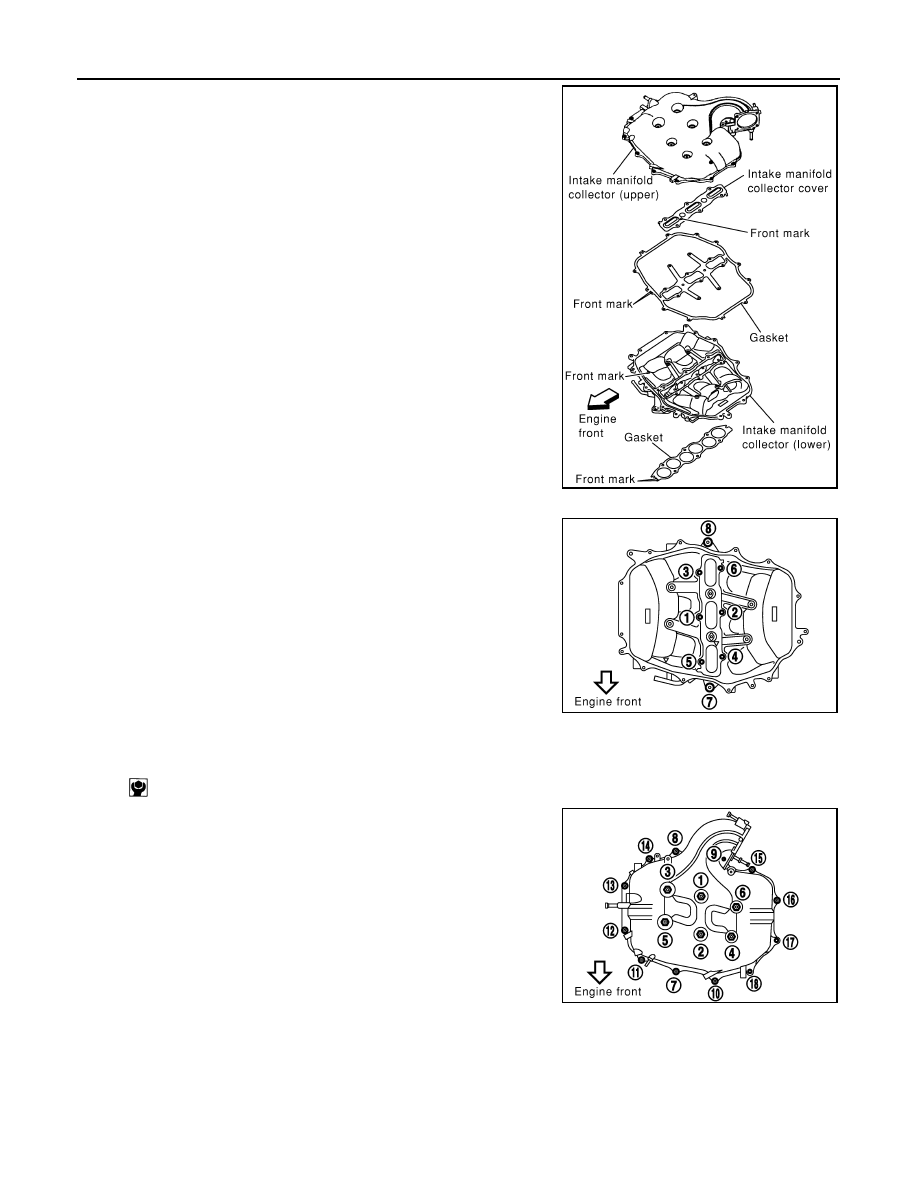
8.
Loosen mounting bolts in reverse order of illustration to remove
intake manifold collector (upper) with power tool.
9.
Remove PCV hose [between intake manifold collector (lower) and rocker cover (right bank)].
10. Loosen mounting bolts in reverse order as shown in the figure,
and remove intake manifold collector cover, gasket, intake man-
ifold collector (lower) and gasket with power tool.
CAUTION:
Cover engine openings to avoid entry of foreign materials.
INSPECTION AFTER REMOVAL
Surface Distortion
• Check the surface distortion of both the intake manifold collector
(upper and lower) mating surfaces with a straightedge and a feeler
gauge.
• If it exceeds the limit, replace intake manifold collector (upper and/
or lower).
INSTALLATION
Note the following, and install in the reverse order of removal.
Part Installation Direction
PBIC0773E
PBIC0774E
Limit
: 0.1 mm (0.004 in)
PBIC0775E
EM-22
< SERVICE INFORMATION >
[VQ35DE]
INTAKE MANIFOLD COLLECTOR
Referring to front marks, install parts shown in figure.
Intake Manifold Collector (Lower)
Tighten mounting bolts in numerical order as shown in the figure.
NOTE:
Tighten mounting bolts to secure gasket (lower), intake manifold col-
lector (lower), gasket (upper), and intake manifold collector cover.
Intake Manifold Collector (Upper)
• If stud bolts were removed, install them and tighten to the specifiedtorque below.
• Shank length under bolt head varies with bolt location. Install
mounting bolts while referring to numbers shown below and in the
figure. (Bolt length does not include pilot portion.)
• Tighten mounting bolts in numerical order as shown in the figure.
Water Hose
• Insert hose by 27 to 32 mm (1.06 to 1.26 in) from connector end.
• Clamp hose at location of 3 to 7 mm (0.12 to 0.28 in) from hose end.
Electric Throttle Control Actuator
• Install gasket with positioning no-protrusion surface upward or downward.
PBIC0776E
PBIC0774E
: 5.9 N·m (0.6 kg-m, 52 in-lb)
Bolt
M6
×
25 mm (0.98 in)
: 7, 8, 10, 11, 13, 14, 15, 16, 18
M6
×
45 mm (1.77 in)
: 2, 4, 5
M6
×
60 mm (2.36 in)
: 1, 3, 6, 9
M6 Nut
: 12, 17
PBIC0773E
INTAKE MANIFOLD COLLECTOR
EM-23
< SERVICE INFORMATION >
[VQ35DE]
C
D
E
F
G
H
I
J
K
L
M
A
EM
N
P
O
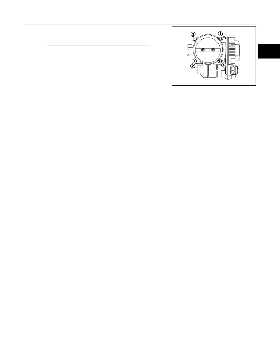
• Tighten in numerical order as shown in the figure.
• Perform the “Throttle Valve Closed Position Learning” when har-
ness connector of electric throttle control actuator is disconnected.
Refer to
EC-85, "Throttle Valve Closed Position Learning"
.
• Perform the “Idle Air Volume Learning” and “Throttle Valve Closed
Position Learning” when electric throttle control actuator is
replaced. Refer to
EC-85, "Idle Air Volume Learning"
.
KBIA0957E
EM-24
< SERVICE INFORMATION >
[VQ35DE]
INTAKE MANIFOLD
INTAKE MANIFOLD
Component
INFOID:0000000001325712
Removal and Installation
INFOID:0000000001325713
REMOVAL
1.
Release fuel pressure. Refer to
2.
Remove intake manifold collectors (upper and lower). Refer to
.
3.
Remove fuel tube and fuel injector assembly. Refer to
4.
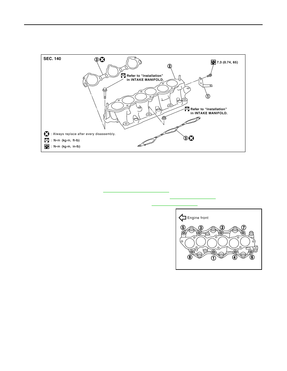
Loosen mounting bolts and nuts in reverse order as shown in
the figure to remove intake manifold with power tool.
5.
Remove gaskets.
CAUTION:
Cover engine openings to avoid entry of foreign materials.
INSPECTION AFTER REMOVAL
Surface Distortion
1.
Harness bracket
2.
Intake manifold
3.
Gasket
SBIA0487E
PBIC0778E
Нет комментариевНе стесняйтесь поделиться с нами вашим ценным мнением.
Текст