Infiniti FX35 / FX45. Manual — part 938

SRS-12
< SERVICE INFORMATION >
TROUBLE DIAGNOSIS
TROUBLE DIAGNOSIS
Trouble Diagnosis Introduction
INFOID:0000000001524161
CAUTION:
• Do not use electrical test equipment on any circuit related to the SRS unless instructed in this Ser-
vice Manual. SRS wiring harnesses can be identified by yellow and/or orange harnesses or harness
connectors.
• Do not repair, splice or modify the SRS wiring harness. If the harness is damaged, replace it with a
new one.
• Keep ground portion clean.
DIAGNOSIS FUNCTION
The SRS self-diagnostic results can be read by using “AIR BAG” warning lamp and/or CONSULT-III.
The User mode is exclusively prepared for the customer (driver). This mode warns the driver of a system mal-
function through the operation of the “AIR BAG” warning lamp.
The Diagnosis mode allows the technician to locate and inspect the malfunctioning part.
The mode applications for the “AIR BAG” warning lamp and CONSULT-III are as follows:
HOW TO PERFORM TROUBLE DIAGNOSIS FOR QUICK AND ACCURATE REPAIR
A good understanding of the malfunction conditions can make troubleshooting faster and more accurate.
In general, each customer feels differently about a malfunction. It is important to fully understand the symp-
toms or conditions for a customer complaint.
Information from Customer
WHAT. . Vehicle model
WHEN. . Date, Frequencies
WHERE. . Road conditions
HOW. . Operating conditions, Symptoms
Preliminary Check
Make sure the following parts are in good order.
• Battery (Refer to
.)
• Fuse (Refer to
SRS-16, "Wiring Diagram - SRS -"
• System component-to-harness connections
Work Flow
OVERALL SEQUENCE
User mode
Diagnosis mode
Display type
“AIR BAG” warning lamp
X
X
ON-OFF operation
CONSULT-III
—
X
Monitoring

TROUBLE DIAGNOSIS
SRS-13
< SERVICE INFORMATION >
C
D
E
F
G
I
J
K
L
M
A
B
SRS
N
O
P
DETAILED FLOW
1.
GET INFORMATION FOR SYMPTOM
Get the detailed information from the customer about the symptom.
>> GO TO 2.
2.
PERFORM PRELIMINARY CHECK
At the begining of inspection, confirm the condition of power supply circuit, check that the battery is charged
and fuses and fusible links are not blown.
Is power supply circuit normal?
YES
>> GO TO 3.
NO
>> Repair or replace the battery and fuse/fusible links.
3.
PERFORM SELF-DIAGNOSIS USING “CONSULT-III” (WITH CONSULT-III)
Check the screen of CONSULT-III.
Is malfunctioning part displayed on CONSULT-III?
YES
>> GO TO 5.
NO
>> Repeat DTC confirmation with diagnostic procedure.
4.
PERFORM SELF-DIAGNOSIS “AIR BAG” WARNING LAMP (WITHOUT CONSULT-III)
Check the warning lamp status.
JMHIA0027GB
SRS-14
< SERVICE INFORMATION >
TROUBLE DIAGNOSIS
Is malfunctioning part detected?
YES
>> GO TO 5.
NO
>> Repeat DTC confirmation with diagnostic procedure.
5.
REPAIR OR REPLACE
Repair or replace the malfunctioning part.
After the malfunctioning is repaired, erase the self-diagnostic result. Refer to
.
>> GO TO 6.
6.
FINAL CHECK DIAGNOSIS MODE AND USER MODE
Check the screen of CONSULT-III and/or Air bag warning lamp status.
Are the malfunctions corrected?
YES
>> INSPECTION END.
NO
>> GO TO 3 or GO TO 4.
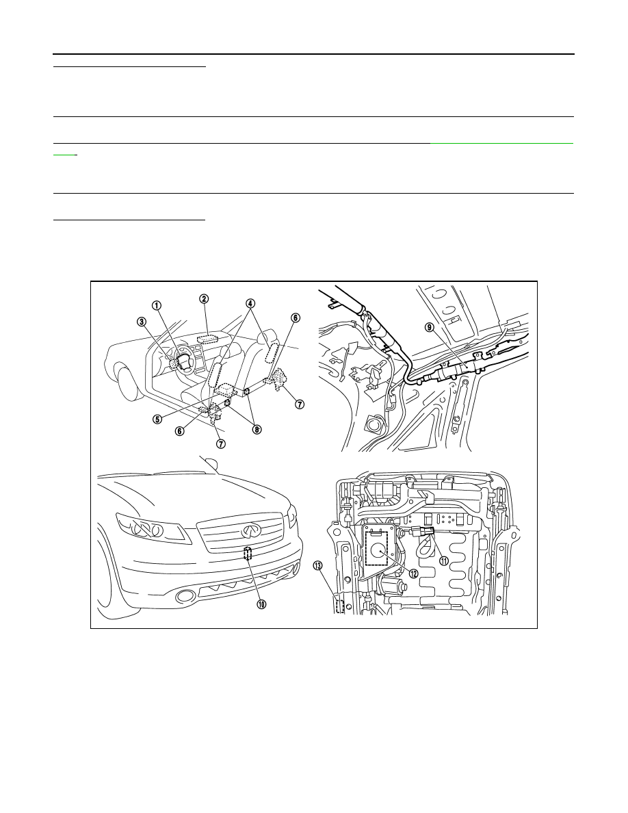
Component Parts Location
INFOID:0000000001524162
PHIA1352E
1. Driver air bag module
2. Front passenger air bag module
3. Spiral cable
4. Front side air bag module (LH/RH)
5. Diagnosis sensor unit
6.
Side air bag (Satellite) sensor (LH/
RH)
7. Seat belt pre-tensioner (LH/RH)
8. Seat belt buckle switch (LH/RH)
9. Side curtain air bag module
10. Crash zone sensor
11.
Occupant classification system sen-
sor
12.
Occupant classification system con-
trol unit
13. Belt tension sensor (passenger side)

TROUBLE DIAGNOSIS
SRS-15
< SERVICE INFORMATION >
C
D
E
F
G
I
J
K
L
M
A
B
SRS
N
O
P
Schematic
INFOID:0000000001524163
THWM0250E
Нет комментариевНе стесняйтесь поделиться с нами вашим ценным мнением.
Текст