Infiniti FX35 / FX45. Manual — part 122
ATC-84
< SERVICE INFORMATION >
TROUBLE DIAGNOSIS
Self-Diagnosis
INFOID:0000000001328194
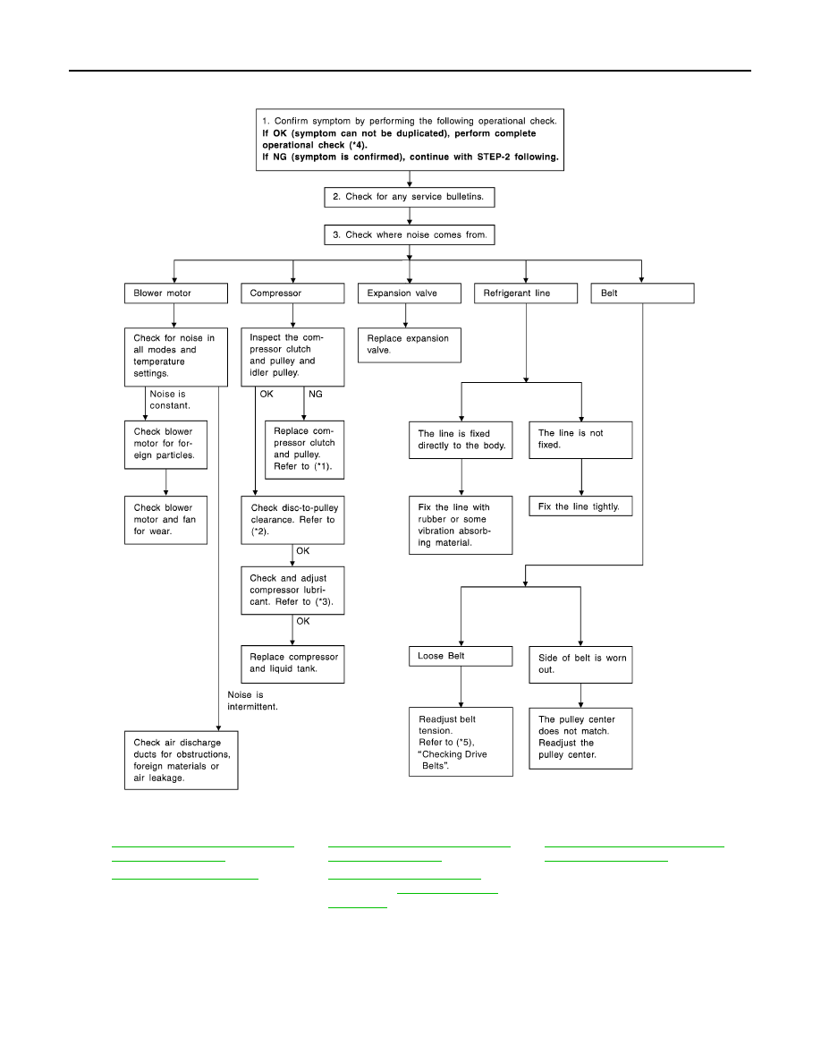
SYMPTOM: Self-diagnosis cannot be performed.
INSPECTION FLOW
*1
ATC-125, "Removal and Installation
of Compressor Clutch"
*2
ATC-125, "Removal and Installation
of Compressor Clutch"
*3
ATC-22, "Maintenance of Lubricant
Quantity in Compressor"
*4
*5
(VQ35DE) or
RJIA3108E
TROUBLE DIAGNOSIS
ATC-85
< SERVICE INFORMATION >
C
D
E
F
G
H
I
K
L
M
A
B
ATC
N
O
P
Memory Function
INFOID:0000000001328195
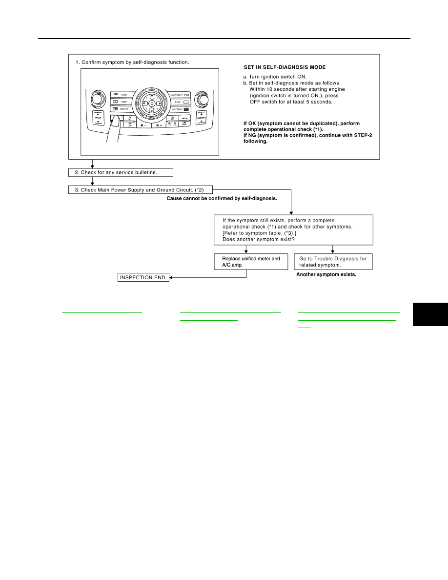
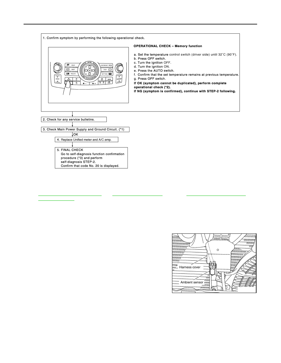
SYMPTOM: Memory function does not operate.
INSPECTION FLOW
*1
*2
ATC-52, "Power Supply and Ground
Circuit for Auto Amp"
*3
ATC-32, "How to Perform Trouble Di-
agnosis for Quick and Accurate Re-
pair"
SJIA1803E
ATC-86
< SERVICE INFORMATION >
TROUBLE DIAGNOSIS
Ambient Sensor Circuit
INFOID:0000000001328196
COMPONENT DESCRIPTION
Ambient Sensor
The ambient sensor is attached on the hood lock stay. It detects
ambient temperature and converts it into a resistance value which is
then input into the unified meter and A/C amp.
AMBIENT TEMPERATURE INPUT PROCESS
The unified meter and A/C amp. includes a processing circuit for the ambient sensor input. However, when the
temperature detected by the ambient sensor increases quickly, the processing circuit retards the unified meter
and A/C amp. function. It only allows the unified meter and A/C amp. to recognize an ambient temperature
increase of 0.33
°
C (0.6
°
F) per 100 seconds.
As an example, consider stopping for a few minutes after high speed driving. Although the actual ambient tem-
perature has not changed, the temperature detected by the ambient sensor will increase. This is because the
heat from the engine compartment can radiate to the front grille area, location of the ambient sensor.
DIAGNOSIS PROCEDURE FOR AMBIENT SENSOR
*1
ATC-52, "Power Supply and Ground
Circuit for Auto Amp"
*2
*3
ATC-43, "Self-Diagnosis Function"
SJIA1595E
RJIA2016E
TROUBLE DIAGNOSIS
ATC-87
< SERVICE INFORMATION >
C
D
E
F
G
H
I
K
L
M
A
B
ATC
N
O
P
SYMPTOM: Ambient sensor circuit is open or shorted. (21 or
−
21 is
indicated on unified meter and A/C amp. as a result of performing
self-diagnosis STEP-2.)
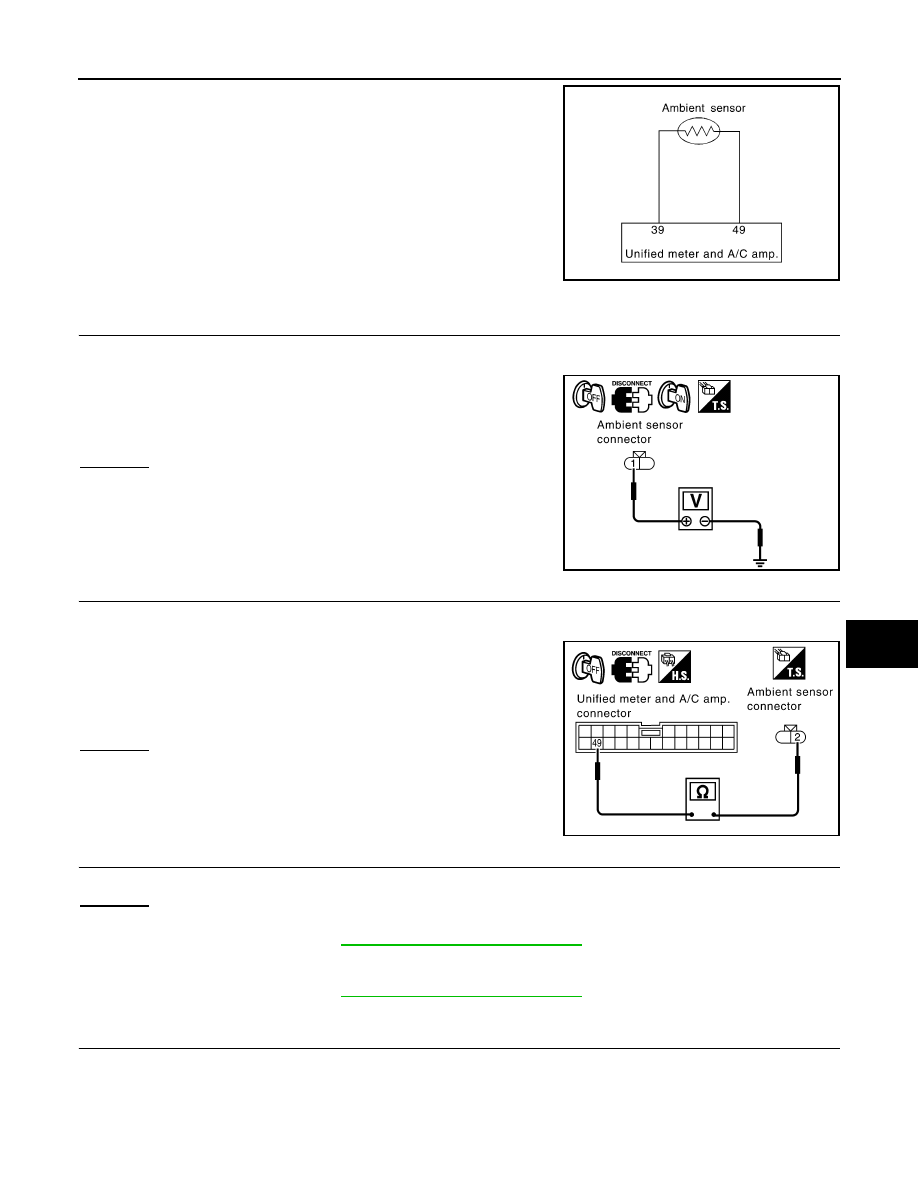
1.
CHECK VOLTAGE BETWEEN AMBIENT SENSOR AND GROUND
1.
Disconnect ambient sensor connector.
2.
Turn ignition switch ON.
3.
Check voltage between ambient sensor harness connector E34
terminal 1 and ground.
OK or NG
OK
>> GO TO 2.
NG
>> GO TO 4.
2.
CHECK CIRCUIT CONTINUITY BETWEEN AMBIENT SENSOR AND UNIFIED METER AND A/C AMP.
1.
Turn ignition switch OFF.
2.
Disconnect unified meter and A/C amp. connector.
3.
Check continuity between ambient sensor harness connector
E34 terminal 2 and unified meter and A/C amp. harness connec-
tor M57 terminal 49.
OK or NG
OK
>> GO TO 3.
NG
>> Repair harness or connector.
3.
CHECK AMBIENT SENSOR
Refer to "Ambient Sensor".
OK or NG
OK
>> 1.
Replace unified meter and A/C amp.
2.
ATC-43, "Self-Diagnosis Function"
and perform self-diagnosis STEP-2.
Confirm that code No. 20 is displayed.
NG
>> 1.
Replace ambient sensor.
2.
ATC-43, "Self-Diagnosis Function"
and perform self-diagnosis STEP-2.
Confirm that code No. 20 is displayed.
4.
CHECK CIRCUIT CONTINUITY BETWEEN AMBIENT SENSOR AND UNIFIED METER AND A/C AMP.
1.
Turn ignition switch OFF.
2.
Disconnect unified meter and A/C amp. connector.
RJIA1461E
1 – Ground
: Approx. 5 V
RJIA2017E
2 – 49
: Continuity should exist.
RJIA2018E
Нет комментариевНе стесняйтесь поделиться с нами вашим ценным мнением.
Текст