Infiniti FX35 / FX45. Manual — part 417
DTC P0850 PNP SWITCH
EC-429
< SERVICE INFORMATION >
[VQ35DE]
C
D
E
F
G
H
I
J
K
L
M
A
EC
N
P
O
DTC P0850 PNP SWITCH
Component Description
INFOID:0000000001326275
When the selector lever position is P or N, park/neutral position (PNP) switch is ON.
ECM detects the position because the continuity of the line (the ON signal) exists.
CONSULT-III Reference Value in Data Monitor Mode
INFOID:0000000001326276
Specification data are reference values.
On Board Diagnosis Logic
INFOID:0000000001326277
DTC Confirmation Procedure
INFOID:0000000001326278
CAUTION:
Always drive vehicle at a safe speed.
NOTE:
If DTC Confirmation Procedure has been previously conducted, always turn ignition switch OFF and wait at
least 10 seconds before conducting the next test.
WITH CONSULT-III
1.
Turn ignition switch ON.
2.
Select “P/N POSI SW” in “DATA MONITOR” mode with CONSULT-III. Then check the “P/N POSI SW” sig-
nal under the following conditions.
If NG, go to
If OK, go to following steps.
3.
Select “DATA MONITOR” mode with CONSULT-III.
4.
Start engine and warm it up to normal operating temperature.
5.
Maintain the following conditions for at least 60 consecutive seconds.
6.
Check 1st trip DTC,
7.
If 1st trip DTC is detected, go to
MONITOR ITEM
CONDITION
SPECIFICATION
P/N POSI SW
• Ignition switch: ON
Selector lever: P or N
ON
Selector lever: Except above
OFF
DTC No.
Trouble diagnosis name
DTC detecting condition
Possible cause
P0850
0850
Park/neutral position
switch
The signal of the park/neutral position (PNP)
switch is not changed in the process of engine
starting and driving.
• Harness or connectors
[Park/neutral position (PNP) switch circuit
is open or shorted.]
• Park/neutral position (PNP) switch
• Unified meter and A/C amp.
Position (Selector lever)
Known-good signal
P or N position
ON
Except above position
OFF
ENG SPEED
1,000 - 6,375 rpm
COOLAN TEMP/S
More than 70
°
C (158
°
F)
B/FUEL SCHDL
2.0 - 31.8 msec
VHCL SPEED SE
More than 64 km/h (40 MPH)
Selector lever
Suitable position
EC-430
< SERVICE INFORMATION >
[VQ35DE]
DTC P0850 PNP SWITCH
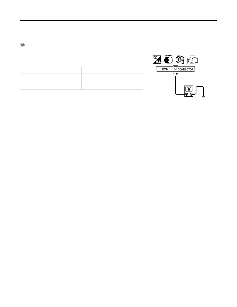
Overall Function Check
INFOID:0000000001326279
Use this procedure to check the overall function of the park/neutral position (PNP) switch circuit. During this
check, a 1st trip DTC might not be confirmed.
WITH GST
1.
Turn ignition switch ON.
2.
Check voltage between ECM terminal 102 (PNP switch signal)
and ground under the following conditions.
3.
If NG, go to
Condition (Selector lever)
Voltage V (Known-good data)
P or N position
Approx. 0
Except above position
BATTERY VOLTAGE
(11 - 14V)
MBIB0043E
DTC P0850 PNP SWITCH
EC-431
< SERVICE INFORMATION >
[VQ35DE]
C
D
E
F
G
H
I
J
K
L
M
A
EC
N
P
O
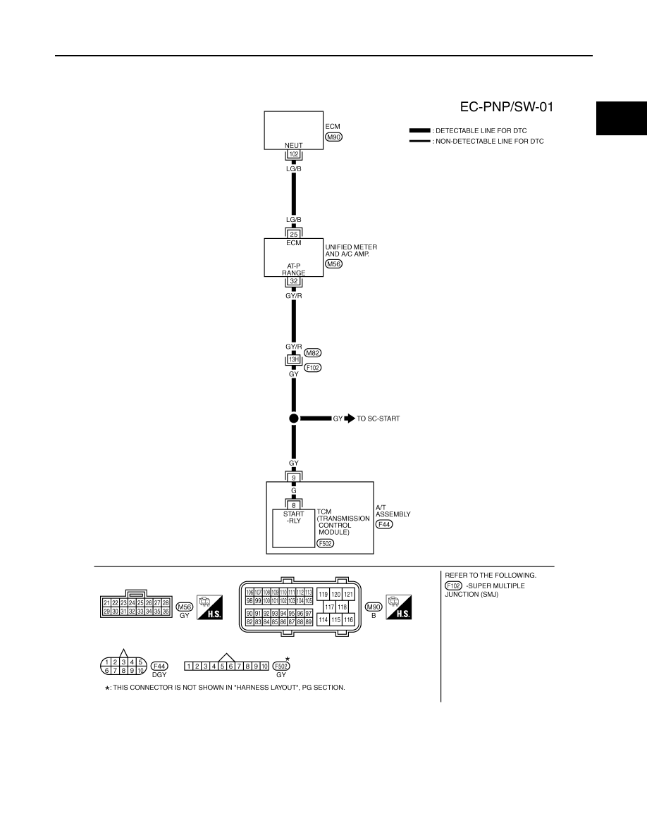
Wiring Diagram
INFOID:0000000001326280
Specification data are reference values and are measured between each terminal and ground.
CAUTION:
Do not use ECM ground terminals when measuring input/output voltage. Doing so may result in dam-
age to the ECM's transistor. Use a ground other than ECM terminals, such as the ground.
TBWM0521E

EC-432
< SERVICE INFORMATION >
[VQ35DE]
DTC P0850 PNP SWITCH
Diagnosis Procedure
INFOID:0000000001326281
1.
CHECK DTC WITH TCM
AT-38, "OBD-II Diagnostic Trouble Code (DTC)"
OK or NG
OK
>> GO TO 2.
NG
>> Repair or replace.
2.
CHECK STARTING SYSTEM
Turn ignition switch OFF, then turn it to START.
Does starter motor operate?
Yes or No
Yes
>> GO TO 3.
No
>> Refer to
.
3.
CHECK PNP SWITCH INPUT SIGNAL CIRCUIT FOR OPEN AND SHORT-I
1.
Turn ignition switch OFF.
2.
Disconnect A/T assembly harness connector.
3.
Disconnect “unified meter and A/C amp.” harness connector.
4.
Check harness continuity between A/T assembly terminal 9 and “unified meter and A/C amp.” terminal 32.
Refer to Wiring Diagram.
5.
Also check harness for short to ground and short to power.
OK or NG
OK
>> GO TO 5.
NG
>> GO TO 4.
4.
DETECT MALFUNCTIONING PART
Check the following.
• Harness connectors F102, M82
• Harness for open or short between A/T assembly and “unified meter and A/C amp.”.
>> Repair open circuit or short to ground or short to power in harness or connectors.
5.
CHECK PNP SWITCH INPUT SIGNAL CIRCUIT FOR OPEN AND SHORT-II
1.
Disconnect ECM harness connector.
2.
Check harness continuity between ECM terminal 102 and “unified meter and A/C amp.” terminal 25.
Refer to Wiring Diagram.
3.
Also check harness for short to ground and short to power.
OK or NG
OK
>> GO TO 6.
NG
>> Repair open circuit or short to ground or short to power in harness or connectors.
6.
CHECK PNP SWITCH INPUT SIGNAL CIRCUIT FOR OPEN AND SHORT-III
TER-
MI-
NAL
NO.
WIRE
COLOR
ITEM
CONDITION
DATA (DC Voltage)
102
LG/B
PNP switch
[Ignition switch: ON]
• Selector lever: P or N
Approximately 0V
[Ignition switch: ON]
• Except above position
BATTERY VOLTAGE
(11 - 14V)
Continuity should exist.
Continuity should exist.
Нет комментариевНе стесняйтесь поделиться с нами вашим ценным мнением.
Текст