Infiniti FX35 / FX45. Manual — part 416
DTC P0643 SENSOR POWER SUPPLY
EC-425
< SERVICE INFORMATION >
[VQ35DE]
C
D
E
F
G
H
I
J
K
L
M
A
EC
N
P
O
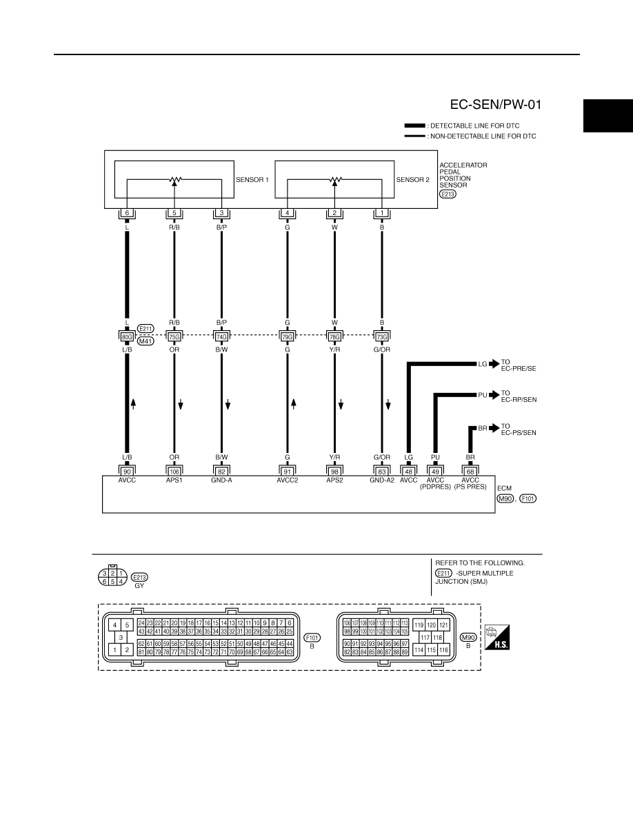
Wiring Diagram
INFOID:0000000001326273
Specification data are reference values and are measured between each terminal and ground.
CAUTION:
Do not use ECM ground terminals when measuring input/output voltage. Doing so may result in dam-
age to the ECM's transistor. Use a ground other than ECM terminals, such as the ground.
TBWM1400E
EC-426
< SERVICE INFORMATION >
[VQ35DE]
DTC P0643 SENSOR POWER SUPPLY
Diagnosis Procedure
INFOID:0000000001326274
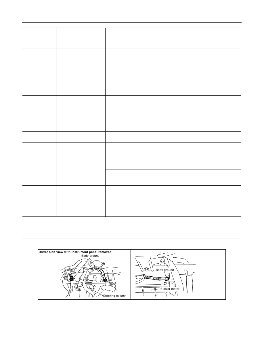
1.
CHECK GROUND CONNECTIONS
1.
Turn ignition switch OFF.
2.
Loosen and retighten ground screw on the body. Refer to
OK or NG
OK
>> GO TO 2.
NG
>> Repair or replace ground connections.
2.
CHECK ACCELERATOR PEDAL POSITION SENSOR 1 POWER SUPPLY CIRCUIT-I
TER-
MI-
NAL
NO.
WIRE
COLOR
ITEM
CONDITION
DATA (DC Voltage)
48
LG
Sensor power supply
(EVAP control system pres-
sure sensor)
[Ignition switch: ON]
Approximately 5V
49
PU
Sensor power supply
(Refrigerant pressure sen-
sor)
[Ignition switch: ON]
Approximately 5V
68
BR
Sensor power supply
(Power steering pressure
sensor)
[Ignition switch: ON]
Approximately 5V
82
B/W
Sensor ground
(APP sensor 1, ASCD steer-
ing switch, ICC steering
switch)
[Engine is running]
• Warm-up condition
• Idle speed
Approximately 0V
83
G/OR
Sensor ground
(APP sensor 2)
[Engine is running]
• Warm-up condition
• Idle speed
Approximately 0V
90
L/B
Sensor power supply
(APP sensor 1)
[Ignition switch: ON]
Approximately 5V
91
G
Sensor power supply
(APP sensor 2)
[Ignition switch: ON]
Approximately 5V
98
Y/R
Accelerator pedal position
sensor 2
[Ignition switch: ON]
• Engine stopped
• Accelerator pedal: Fully released
0.15 - 0.60V
[Ignition switch: ON]
• Engine stopped
• Accelerator pedal: Fully depressed
1.95 - 2.40V
106
OR
Accelerator pedal position
sensor 1
[Ignition switch: ON]
• Engine stopped
• Accelerator pedal: Fully released
0.5 - 1.0V
[Ignition switch: ON]
• Engine stopped
• Accelerator pedal: Fully depressed
3.9 - 4.7V
PBIB2625E
DTC P0643 SENSOR POWER SUPPLY
EC-427
< SERVICE INFORMATION >
[VQ35DE]
C
D
E
F
G
H
I
J
K
L
M
A
EC
N
P
O
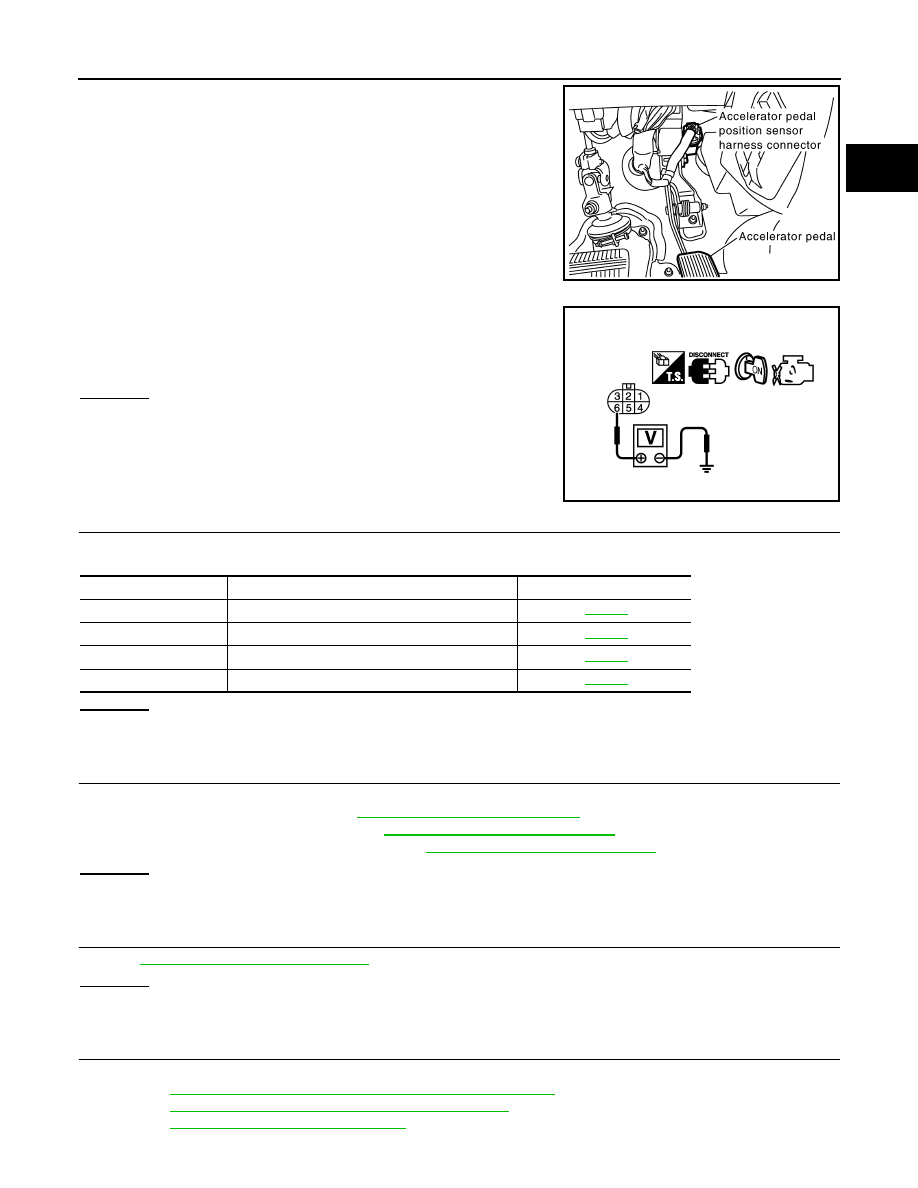
1.
Disconnect accelerator pedal position (APP) sensor harness
connector.
2.
Turn ignition switch ON.
3.
Check voltage between APP sensor terminal 6 and ground with
CONSULT-III or tester.
OK or NG
OK
>> GO TO 5.
NG
>> GO TO 3.
3.
CHECK SENSOR POWER SUPPLY CIRCUITS
Check harness for short to power and short to ground, between the following terminals.
OK or NG
OK
>> GO TO 6.
NG
>> Repair short to ground or short to power in harness or connectors.
4.
CHECK COMPONENTS
Check the following.
• Refrigerant pressure sensor (Refer to
ATC-69, "Magnet Clutch Circuit"
.)
• Power steering pressure sensor (Refer to
EC-416, "Component Inspection"
• EVAP control system pressure sensor (Refer to
EC-373, "Component Inspection"
.)
OK or NG
OK
>> GO TO 7.
NG
>> Replace malfunctioning component.
5.
CHECK ACCELERATOR PEDAL POSITION SENSOR
EC-511, "Component Inspection"
.
OK or NG
OK
>> GO TO 7.
NG
>> GO TO 6.
6.
REPLACE ACCELERATOR PEDAL ASSEMBLY
1.
Replace accelerator pedal assembly.
2.
EC-85, "Accelerator Pedal Released Position Learning"
3.
EC-85, "Throttle Valve Closed Position Learning"
.
4.
EC-85, "Idle Air Volume Learning"
PBIB1580E
Voltage: Approximately 5V
PBIB0914E
ECM terminal
Sensor terminal
Reference Wiring Diagram
90
APP sensor terminal 6
49
Refrigerant pressure sensor terminal 1
68
PSP sensor terminal 1
48
EVAP control system pressure sensor terminal 3
Нет комментариевНе стесняйтесь поделиться с нами вашим ценным мнением.
Текст