Infiniti FX35 / FX45. Manual — part 442

DTC P2138 APP SENSOR
EC-529
< SERVICE INFORMATION >
[VQ35DE]
C
D
E
F
G
H
I
J
K
L
M
A
EC
N
P
O
• Harness for open or short between ECM and APP sensor
>> Repair open circuit or short to ground or short to power in harness or connectors.
7.
CHECK ACCELERATOR PEDAL POSITION SENSOR 2 POWER SUPPLY CIRCUIT-III
Check the following.
• Harness for short to power and short to ground, between the following terminals.
OK or NG
OK
>> GO TO 8.
NG
>> Repair open circuit or short to ground or short to power in harness connectors.
8.
CHECK THROTTLE POSITION SENSOR
EC-306, "Component Inspection"
OK or NG
OK
>> GO TO 16.
NG
>> GO TO 9.
9.
REPLACE ELECTRIC THROTTLE CONTROL ACTUATOR
1.
Replace electric throttle control actuator.
2.
EC-85, "Throttle Valve Closed Position Learning"
.
3.
EC-85, "Idle Air Volume Learning"
>> INSPECTION END
10.
CHECK ACCELERATOR PEDAL POSITION SENSOR GROUND CIRCUIT FOR OPEN AND SHORT
1.
Turn ignition switch OFF.
2.
Disconnect ECM harness connector.
3.
Check harness continuity between the following;
APP sensor terminals 3 and ECM terminal 82,
APP sensor terminal 1 and ECM terminal 83.
Refer to Wiring Diagram.
4.
Also check harness for short to ground and short to power.
OK or NG
OK
>> GO TO 12.
NG
>> GO TO 11.
11.
DETECT MALFUNCTIONING PART
Check the following.
• Harness connectors E211, M41
• Harness for open or short between ECM and APP sensor
>> Repair open circuit or short to ground or short to power in harness or connectors.
12.
CHECK ACCELERATOR PEDAL POSITION SENSOR INPUT SIGNAL CIRCUIT FOR OPEN AND
SHORT
1.
Check harness continuity between the following;
ECM terminal 106 and APP sensor terminal 5,
ECM terminal 98 and APP sensor terminal 2.
Refer to Wiring Diagram.
ECM terminal
Sensor terminal
Reference Wiring Diagram
91
APP sensor terminal 4
47
Electric throttle control actuator terminal 1
Continuity should exist.
EC-530
< SERVICE INFORMATION >
[VQ35DE]
DTC P2138 APP SENSOR
2.
Also check harness for short to ground and short to power.
OK or NG
OK
>> GO TO 14.
NG
>> GO TO 13.
13.
DETECT MALFUNCTIONING PART
Check the following.
• Harness connectors E211, M41
• Harness for open or short between ECM and APP sensor
>> Repair open circuit or short to ground or short to power in harness or connectors.
14.
CHECK ACCELERATOR PEDAL POSITION SENSOR
EC-530, "Component Inspection"
OK or NG
OK
>> GO TO 16.
NG
>> GO TO 15.
15.
REPLACE ACCELERATOR PEDAL ASSEMBLY
1.
Replace accelerator pedal assembly.
2.
EC-85, "Accelerator Pedal Released Position Learning"
3.
EC-85, "Throttle Valve Closed Position Learning"
.
4.
EC-85, "Idle Air Volume Learning"
>> INSPECTION END
16.
CHECK INTERMITTENT INCIDENT
>> INSPECTION END
Component Inspection
INFOID:0000000001326417
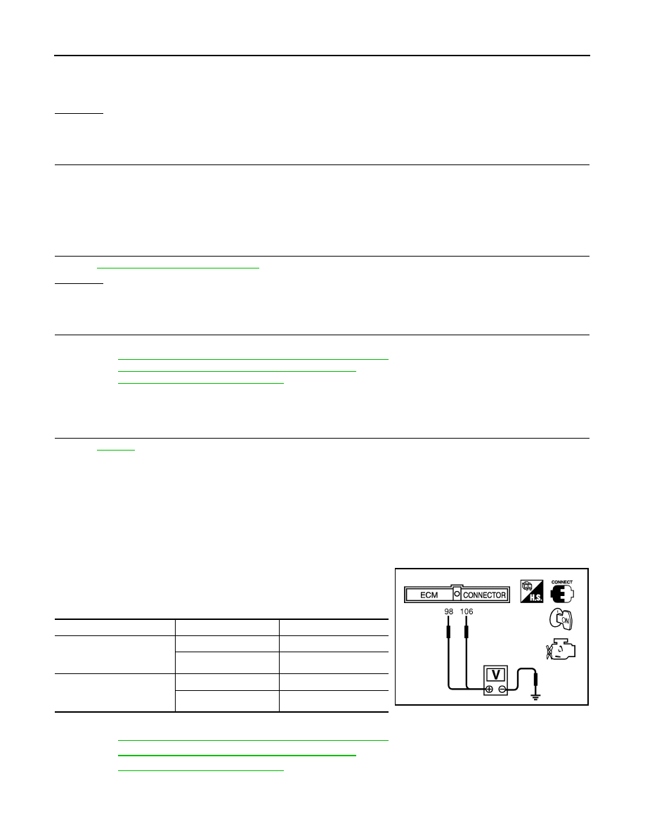
ACCELERATOR PEDAL POSITION SENSOR
1.
Reconnect all harness connectors disconnected.
2.
Turn ignition switch ON.
3.
Check voltage between ECM terminals 106 (APP sensor 1 sig-
nal), 98 (APP sensor 2 signal) and ground under the following
conditions.
4.
If NG, replace accelerator pedal assembly and go to next step.
5.
EC-85, "Accelerator Pedal Released Position Learning"
6.
EC-85, "Throttle Valve Closed Position Learning"
.
7.
EC-85, "Idle Air Volume Learning"
Continuity should exist.
Terminal
Accelerator pedal
Voltage
106
(Accelerator pedal position
sensor 1)
Fully released
0.5 - 1.0V
Fully depressed
3.9 - 4.7V
98
(Accelerator pedal position
sensor 2)
Fully released
0.15 - 0.60V
Fully depressed
1.95 - 2.40V
MBIB0023E
DTC P2138 APP SENSOR
EC-531
< SERVICE INFORMATION >
[VQ35DE]
C
D
E
F
G
H
I
J
K
L
M
A
EC
N
P
O
Removal and Installation
INFOID:0000000001326418
ACCELERATOR PEDAL
.
EC-532
< SERVICE INFORMATION >
[VQ35DE]
DTC P2A00, P2A03 A/F SENSOR 1
DTC P2A00, P2A03 A/F SENSOR 1
Component Description
INFOID:0000000001326419
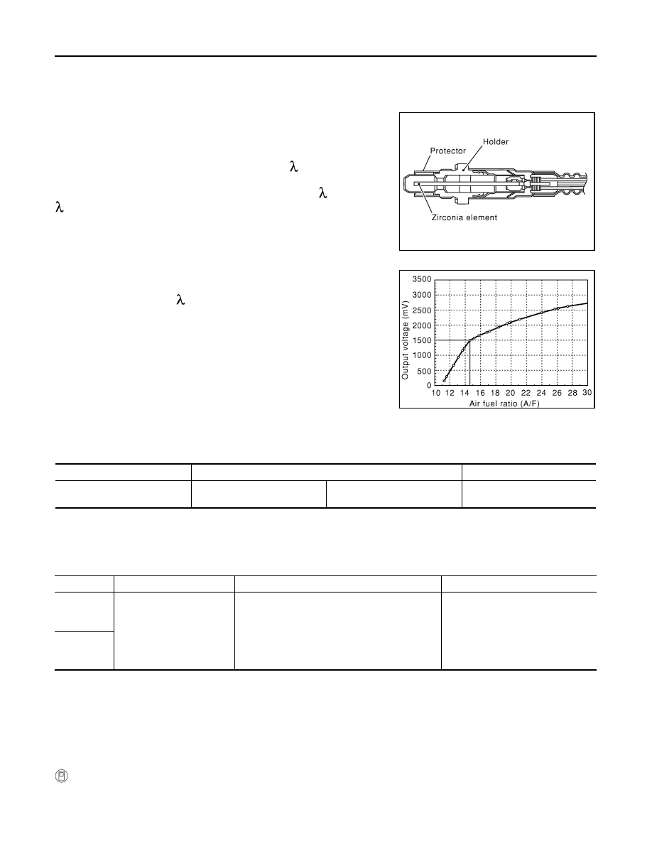
The air fuel ratio (A/F) sensor is a planar dual-cell limit current sen-
sor. The sensor element of the air fuel ratio (A/F) sensor is the com-
bination of a Nernst concentration cell (sensor cell) with an oxygen-
pump cell, which transports ions. It has a heater in the element.
The sensor is capable of precise measurement = 1, but also in the
lean and rich range. Together with its control electronics, the sensor
outputs a clear, continuous signal throughout a wide range (0.7 <
< air).
The exhaust gas components diffuse through the diffusion gap at the
electrode of the oxygen pump and Nernst concentration cell, where
they are brought to thermodynamic balance.
An electronic circuit controls the pump current through the oxygen-
pump cell so that the composition of the exhaust gas in the diffusion
gap remains constant at = 1. Therefore, the air fuel ratio (A/F) sen-
sor is able to indicate air/fuel ratio by this pumping of current. In
addition, a heater is integrated in the sensor to ensure the required
operating temperature of 700 - 800
°
C (1,292 - 1,472
°
F).
CONSULT-III Reference Value in Data Monitor Mode
INFOID:0000000001326420
Specification data are reference values.
On Board Diagnosis Logic
INFOID:0000000001326421
To judge the malfunction, the A/F signal computed by ECM from the air fuel ratio (A/F) sensor 1 signal is mon-
itored not to be shifted to LEAN side or RICH side.
DTC Confirmation Procedure
INFOID:0000000001326422
NOTE:
If DTC Confirmation Procedure has been previously conducted, always turn ignition switch OFF and wait at
least 10 seconds before conducting the next test.
TESTING CONDITION:
Before performing the following procedure, confirm that battery voltage is more than 11V at idle.
WITH CONSULT-III
1.
Start engine and warm it up to normal operating temperature.
2.
Turn ignition switch OFF and wait at least 10 seconds.
SEF579Z
SEF580Z
MONITOR ITEM
CONDITION
SPECIFICATION
A/F SEN1 (B1)
A/F SEN1 (B2)
• Engine: After warming up
Maintaining engine speed at
2,000 rpm
Fluctuates around 1.5V
DTC No.
Trouble diagnosis name
DTC detecting condition
Possible Cause
P2A00
2A00
(Bank 1)
Air fuel ratio (A/F) sensor 1
lean shift monitoring
• The output voltage computed by ECM from the
air fuel ratio (A/F) sensor 1 signal is shifted to
the lean side for a specified period.
• The A/F signal computed by ECM from the air
fuel ratio (A/F) sensor 1 signal is shifted to the
rich side for a specified period.
• Air fuel ratio (A/F) sensor 1
• Air fuel ratio (A/F) sensor 1 heater
• Fuel pressure
• Fuel injector
• Intake air leaks
P2A03
2A03
(Bank 2)
Нет комментариевНе стесняйтесь поделиться с нами вашим ценным мнением.
Текст