Infiniti FX35 / FX45. Manual — part 443
DTC P2A00, P2A03 A/F SENSOR 1
EC-533
< SERVICE INFORMATION >
[VQ35DE]
C
D
E
F
G
H
I
J
K
L
M
A
EC
N
P
O
3.
Turn ignition switch ON and select “SELF-LEARNING CONT” in “WORK SUPPORT” mode with CON-
SULT-III.
4.
Clear the self-learning coefficient by touching “CLEAR”.
5.
Turn ignition switch OFF and wait at least 10 seconds.
6.
Start engine and keep the engine speed between 3,500 and 4,000 rpm for 1 minute under no load.
7.
Let engine idle for 1 minute.
8.
Keep engine speed between 2,500 and 3,000 rpm for 20 minutes.
9.
Check 1st trip DTC.
10. If 1st trip DTC is detected, go to
WITH GST
1.
Start engine and warm it up to normal operating temperature.
2.
Turn ignition switch OFF and wait at least 10 seconds.
3.
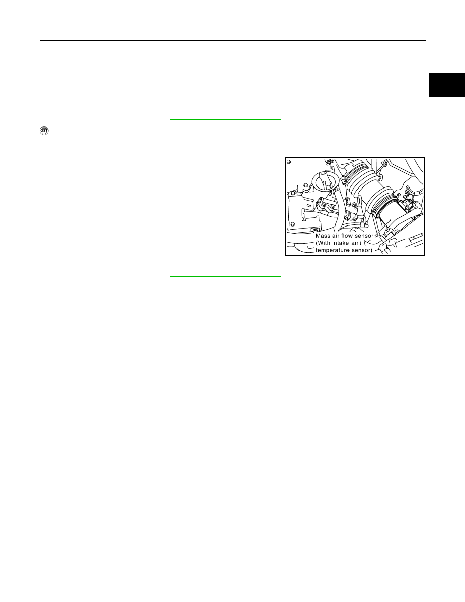
Disconnect mass air flow sensor harness connector.
4.
Start engine and let it idle for at least 5 seconds.
5.
Stop engine and reconnect mass air flow sensor harness con-
nector.
6.
Select Service $03 with GST and make sure that DTC P0102 is
detected.
7.
Select Service $04 with GST and erase the DTC P0102.
8.
Start engine and keep the engine speed between 3,500 and
4,000 rpm for 1 minute under no load.
9.
Let engine idle for 1 minute.
10. Keep engine speed between 2,500 and 3,000 rpm for 20 min-
utes.
11. Select Service $07 with GST.
If 1st trip DTC is detected, go to
PBIB1565E
EC-534
< SERVICE INFORMATION >
[VQ35DE]
DTC P2A00, P2A03 A/F SENSOR 1
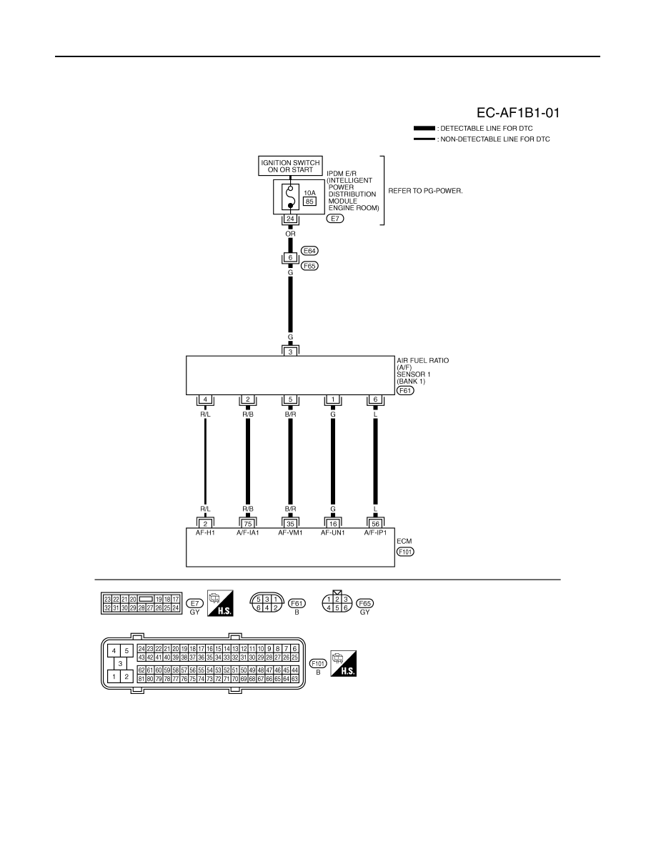
Wiring Diagram
INFOID:0000000001326423
BANK 1
Specification data are reference values and are measured between each terminal and ground.
Pulse signal is measured by CONSULT-III.
CAUTION:
TBWM1598E
DTC P2A00, P2A03 A/F SENSOR 1
EC-535
< SERVICE INFORMATION >
[VQ35DE]
C
D
E
F
G
H
I
J
K
L
M
A
EC
N
P
O
Do not use ECM ground terminals when measuring input/output voltage. Doing so may result in dam-
age to the ECM's transistor. Use a ground other than ECM terminals, such as the ground.
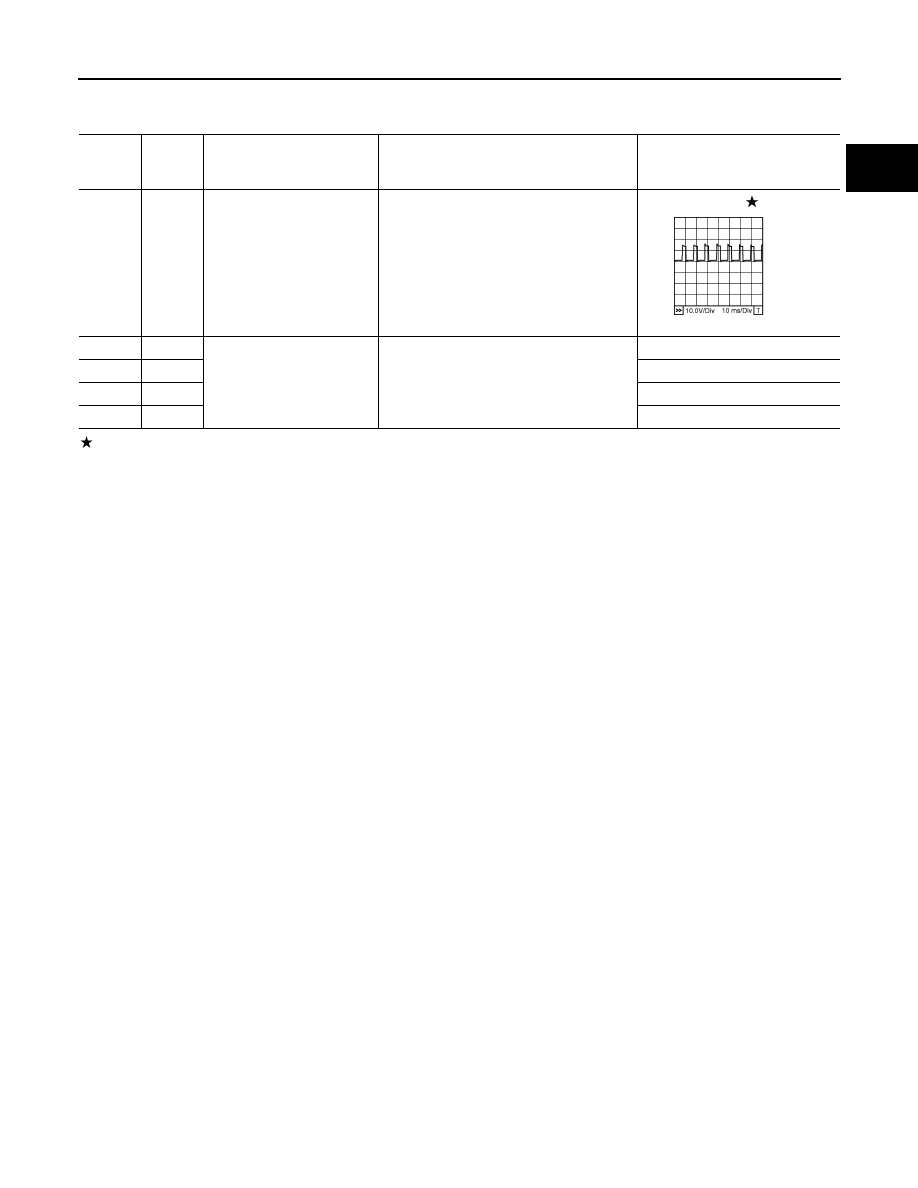
: Average voltage for pulse signal (Actual pulse signal can be confirmed by oscilloscope.)
TERMI-
NAL
NO.
WIRE
COLOR
ITEM
CONDITION
DATA (DC Voltage)
2
R/L
A/F sensor 1 heater
(bank 1)
[Engine is running]
• Warm-up condition
• Idle speed
Approximately 5V
16
G
A/F sensor 1 (bank 1)
[Engine is running]
• Warm-up condition
• Idle speed
Approximately 3.1V
35
B/R
Approximately 2.6V
56
L
Approximately 2.3V
75
R/B
Approximately 2.3V
PBIB1584E
EC-536
< SERVICE INFORMATION >
[VQ35DE]
DTC P2A00, P2A03 A/F SENSOR 1
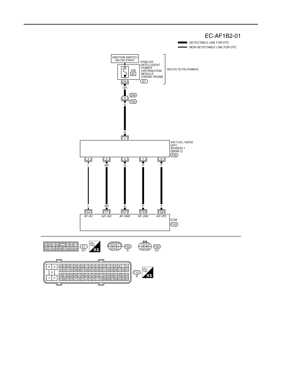
BANK 2
Specification data are reference values and are measured between each terminal and ground.
Pulse signal is measured by CONSULT-III.
CAUTION:
Do not use ECM ground terminals when measuring input/output voltage. Doing so may result in dam-
age to the ECM's transistor. Use a ground other than ECM terminals, such as the ground.
TBWM1599E
Нет комментариевНе стесняйтесь поделиться с нами вашим ценным мнением.
Текст