Infiniti FX35 / FX45. Manual — part 228
VEHICLE SECURITY (THEFT WARNING) SYSTEM
BL-179
< SERVICE INFORMATION >
C
D
E
F
G
H
J
K
L
M
A
B
BL
N
O
P
OK or NG
OK
>> Door switch circuit is OK, and go to “1 – 2 HOOD SWITCH CHECK”.
NG
>> GO TO 2.
2.
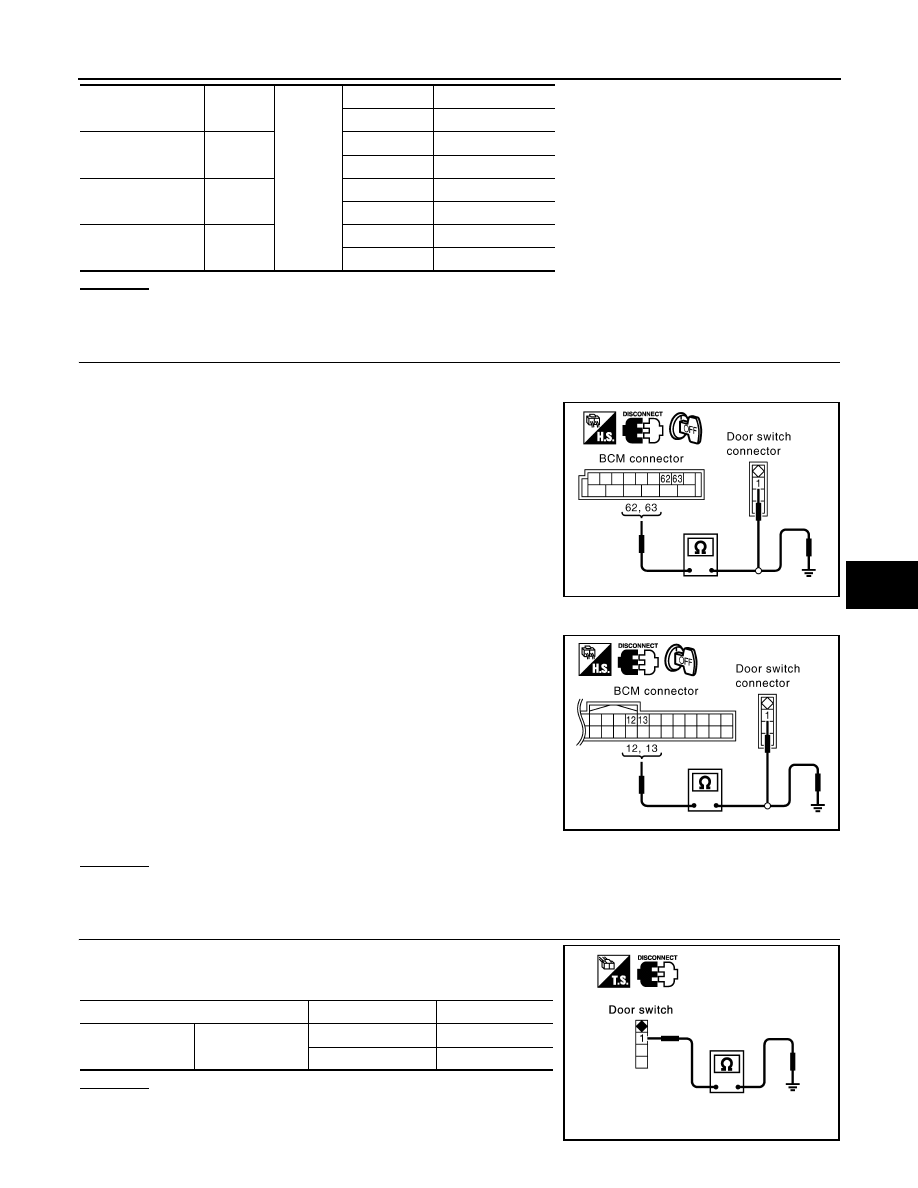
CHECK HARNESS CONTINUITY
1.
Turn ignition switch OFF.
2.
Disconnect BCM and door switches connector.
3.
Check continuity between BCM connector B14 terminals 62, 63
and door switch connector B26, B46 terminal 1, and ground.
4.
Check continuity between BCM connector M3 terminals 12, 13
and door switch connector B36, B206 terminal 1, and ground.
OK or NG
OK
>> GO TO 3.
NG
>> Repair or replace harness.
3.
CHECK DOOR SWITCH
Check continuity between each door switch terminal 1 and ground
part of door switch.
OK or NG
OK
>> GO TO 4.
NG
>> Replace malfunctioning door switch.
Front door switch
driver side
62 (W)
Ground
OPEN
0
CLOSE
Battery voltage
Front door switch
passenger side
12 (P/B)
OPEN
0
CLOSE
Battery voltage
Rear door switch
LH
63 (P)
OPEN
0
CLOSE
Battery voltage
Rear door switch
RH
13 (P/L)
OPEN
0
CLOSE
Battery voltage
BCM – Front door switch (driver side)
62 (W) – 1 (W)
: Continuity should exist.
BCM – Rear door switch LH
63 (P) – 1 (P)
: Continuity should exist.
BCM – Ground
62 (W) – Ground
: Continuity should not exist.
63 (P) – Ground
: Continuity should not exist.
PIIA6225E
BCM – Front door switch (passenger side)
12 (P/B) – 1 (SB)
: Continuity should exist.
BCM – Rear door switch RH
13 (P/L) – 1 (P)
: Continuity should exist.
BCM – Ground
12 (P/B) – Ground
: Continuity should not exist.
13 (P/L) – Ground
: Continuity should not exist.
PIIA6224E
Terminal
Condition
Continuity
1
Ground part of
door switch
Pushed
No
Released
Yes
PIIA3351E
BL-180
< SERVICE INFORMATION >
VEHICLE SECURITY (THEFT WARNING) SYSTEM
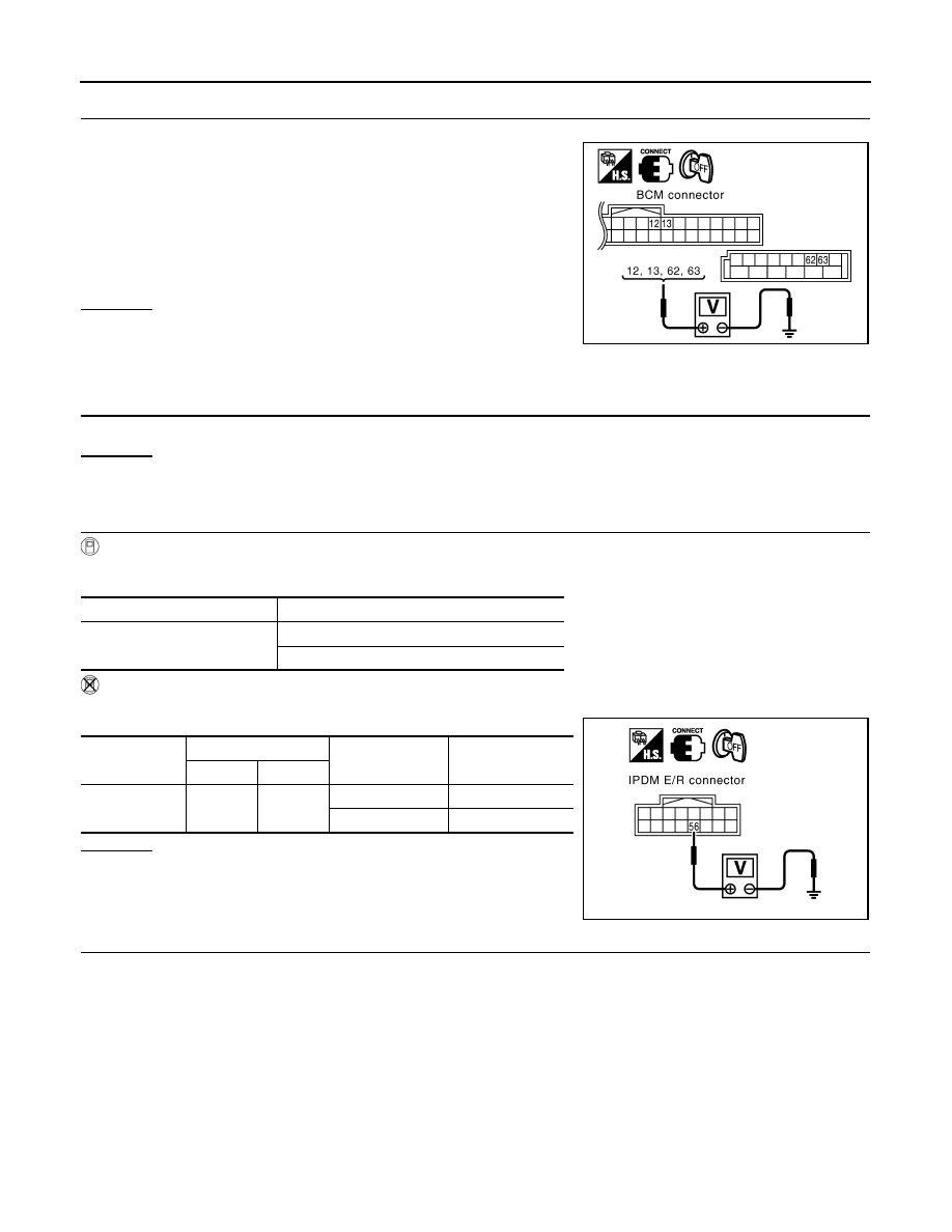
4.
CHECK BCM OUTPUT SIGNAL
1.
Connect BCM connector.
2.
Check voltage between BCM connector M3, B14 terminals 12,
13, 62, 63 and ground.
OK or NG
OK
>> Check condition of harness and connector.
NG
>> Replace BCM.
1 – 2 HOOD SWITCH CHECK
1.
CHECK HOOD SWITCH
Check hood switch and hood fitting condition.
OK or NG
OK
>> GO TO 2.
NG
>> Adjust installation of hood switch.
2.
CHECK HOOD SWITCH INPUT SIGNAL
With CONSULT-III
Check (“HOOD SW”) in “DATA MONITOR” mode with CONSULT-III.
Without CONSULT-III
Check voltage between IPDM E/R connector and ground.
OK or NG
OK
>> Hood switch is OK, and go to “1 – 3 BACK DOOR
SWITCH CHECK”.
NG
>> GO TO 3.
3.
CHECK HOOD SWITCH
1.
Turn ignition switch OFF.
2.
Disconnect hood switch connector.
12 (P/B) – Ground
: Battery voltage
13 (P/L) – Ground
: Battery voltage
62 (W) – Ground
: Battery voltage
63 (P) – Ground
: Battery voltage
PIIA6223E
Monitor item
Condition
HOOD SW
OPEN
: ON
CLOSE
: OFF
Connector
Terminals (Wire color)
Condition
Voltage (V)
(Approx.)
(+)
(-)
E9
56 (LG)
Ground
OPEN
0
CLOSE
Battery voltage
PIIA6228E
VEHICLE SECURITY (THEFT WARNING) SYSTEM
BL-181
< SERVICE INFORMATION >
C
D
E
F
G
H
J
K
L
M
A
B
BL
N
O
P
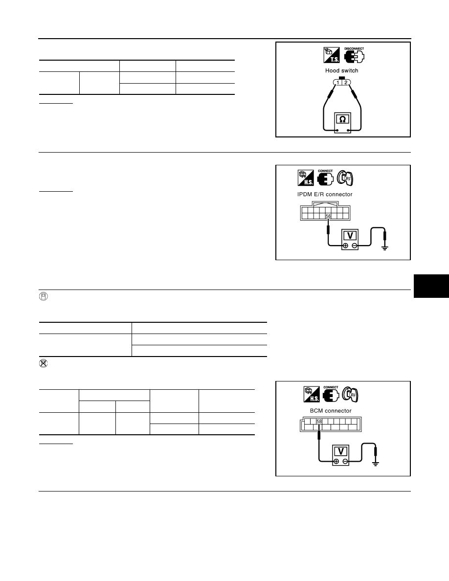
3.
Check continuity between hood switch terminals 1 and 2.
OK or NG
OK
>> GO TO 4.
NG
>> Replace hood switch.
4.
CHECK IPDM E/R OUTPUT SIGNAL
Check voltage between IPDM E/R connector and ground.
OK or NG
OK
>>
Check the following.
• Hood switch ground circuit.
• Harness for open or short between hood switch and
IPDM E/R.
NG
>> Replace IPDM E/R
1 – 3 BACK DOOR SWITCH CHECK
1.
CHECK BACK DOOR SWITCH INPUT SIGNAL
With CONSULT-III
Check (“BACK DOOR SW”) in “DATA MONITOR” mode with CONSULT-III.
Without CONSULT-III
Check voltage between BCM connector and ground.
OK or NG
OK
>> Back door switch circuit is OK.
NG
>> GO TO 2.
2.
CHECK HARNESS CONTINUITY
1.
Turn ignition switch OFF.
2.
Disconnect BCM and back door closure motor connector.
Terminals
Condition
Continuity
1
2
Pressed
No
Released
Yes
PIIA2498E
56 (LG) – Ground
: Battery voltage
PIIA6228E
Monitor item
Condition
BACK DOOR SW
OPEN
: ON
CLOSE
: OFF
Connector
Terminals (Wire color)
Condition
Voltage (V)
(Approx.)
(+)
(–)
B14
58 (L)
Ground
OPEN
0
CLOSE
9
PIIA6229E

BL-182
< SERVICE INFORMATION >
VEHICLE SECURITY (THEFT WARNING) SYSTEM
3.
Check continuity between BCM connector B14 terminal 58 and
back door closure motor connector D109 terminal 7.
4.
Check continuity between BCM connector B14 terminal 58 and
ground.
OK or NG
OK
>> GO TO 3.
NG
>> Repair or replace harness.
3.
CHECK GROUND CIRCUIT
Check continuity between back door closure motor connector D109
terminal 8 and ground.
OK or NG
OK
>> GO TO 4.
NG
>> Repair or replace harness.
4.
CHECK BACK DOOR SWITCH
Check continuity between back door closure motor D109 terminals 7
and 8.
OK or NG
OK
>> GO TO 5.
NG
>> Replace back door closure motor.
5.
CHECK BCM OUTPUT SIGNAL
1.
Connect BCM connector.
2.
Check voltage between BCM connector B14 terminal 58 and ground.
OK or NG
OK
>> Check condition of harness and connector.
NG
>> Replace BCM.
Diagnosis Procedure 2
INFOID:0000000001327917
SECURITY INDICATOR LAMP CHECK
1.
SECURITY INDICATOR LAMP ACTIVE TEST
58 (L) – 7 (L)
: Continuity should exist.
58 (L) – Ground
: Continuity should not exist.
PIIA6226E
8 (B) – Ground
: Continuity should exist.
PIIA6170E
Terminals
Back door condition
Continuity
7
8
Open
Yes
Close
No
PIIA9934E
58 (L) – Ground
: Approx. 9V
PIIA6229E
Нет комментариевНе стесняйтесь поделиться с нами вашим ценным мнением.
Текст