Infiniti FX35 / FX45. Manual — part 113

ATC-48
< SERVICE INFORMATION >
TROUBLE DIAGNOSIS
When performing indoors, aim a light (more than 60 W) at sunload sensor, otherwise code No. 25 will indicate
despite that sunload sensor is functioning properly.
>> INSPECTION END
14.
CHECK MALFUNCTIONING DOOR MOTOR POSITION SWITCH
Mode and/or intake door motor PBR(s) is/are malfunctioning.
(If two or more mode or intake door motors malfunction, corresponding code Nos. indicates 1 second each.)
*1: If mode door motor harness connector is disconnected, the following display pattern will appear.
31
→
32
→
33
→
34
→
35
→
36
→
Return to 31
*2: If intake door motor harness connector is disconnected, the following display pattern will appear.
37
→
38
→
39
→
Return to 37
*3: FOOT position during automatic control. Refer to "AUXILIARY MECHANISM: FOOT POSITION SETTING
TRIMMER".
>> INSPECTION END
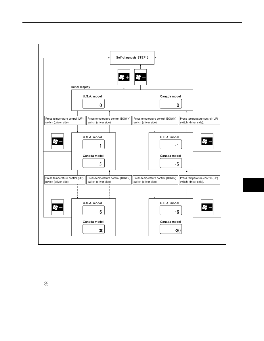
AUXILIARY MECHANISM: TEMPERATURE SETTING TRIMMER
The trimmer compensates for differences in range of
±
3
°
C (
±
6
°
F) between temperature setting (displayed dig-
itally) and temperature felt by customer.
Operating procedures for this trimmer are as follows:
1.
Begin self-diagnosis STEP-5 mode. Refer to "Self-diagnosis Function".
2.
Press (fan) UP switch to set system in auxiliary mode.
3.
Display shows “61” in auxiliary mechanism. It takes approximately 3 seconds to enable setting operation.
SJIA1781E
Code No.
*1 *2
Mode or intake door position
Reference page
31
VENT
Mode door motor
ATC-57, "Mode Door Motor Circuit"
32
B/L 1
33
B/L 2
34
FOOT
*3
35
D/F
36
DEF
37
FRE
Intake door motor
ATC-62, "Intake Door Motor Circuit"
38
20% FRE
39
REC
SJIA1782E
TROUBLE DIAGNOSIS
ATC-49
< SERVICE INFORMATION >
C
D
E
F
G
H
I
K
L
M
A
B
ATC
N
O
P
4.
Press temperature control switch (driver side) as desired. Temperature will change at a rate of 0.5
°
C
(1.0
°
F) each time a switch is pressed.
CAUTION:
A decimal point is not indicated on the display.
When battery cable is disconnected or battery voltage is below 10 V, trimmer operation is canceled. Tempera-
ture set becomes that of initial condition, i.e. 0
°
C (0
°
F).
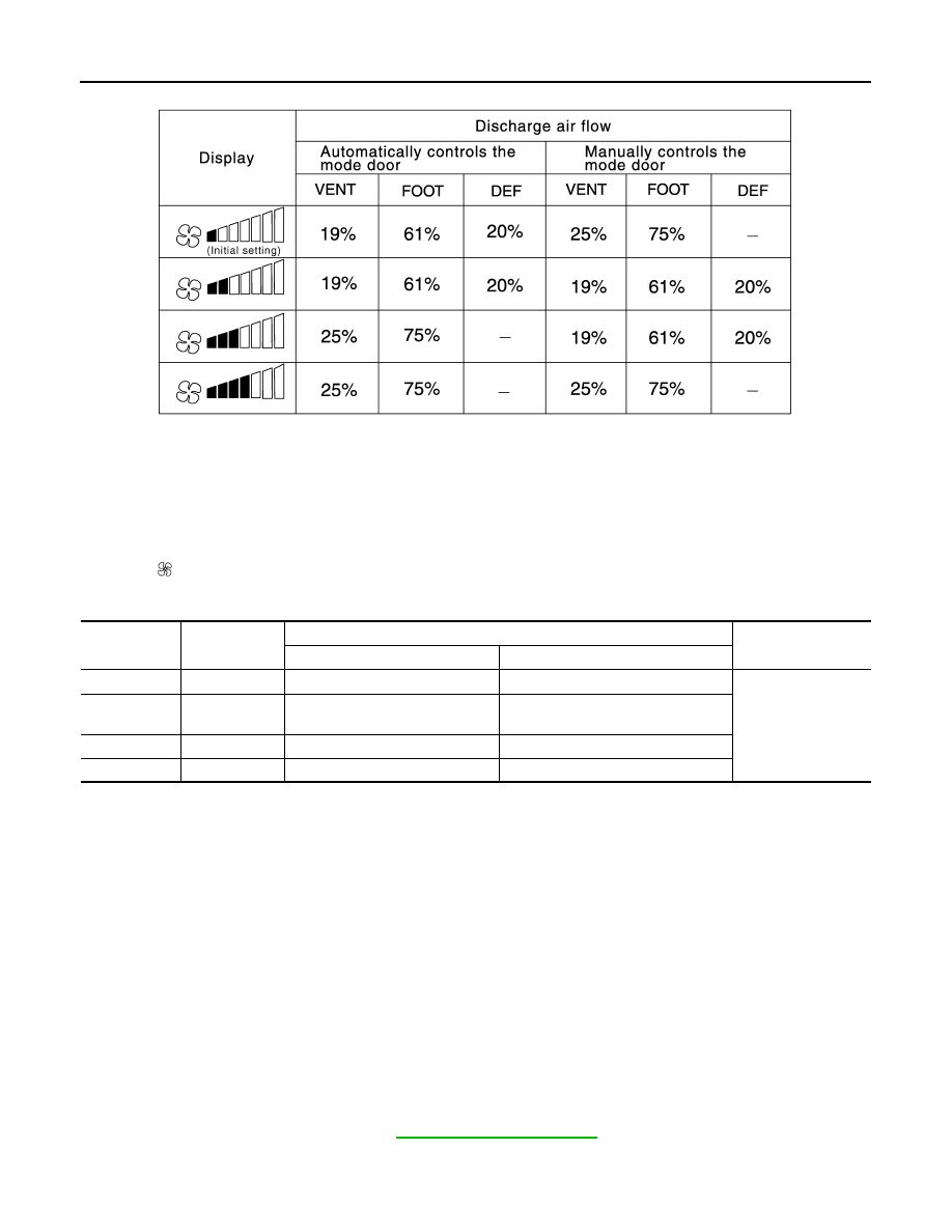
AUXILIARY MECHANISM: FOOT POSITION SETTING TRIMMER
Wind distribution ratio in FOOT mode can be set.
Operating procedures for this trimmer are as follows:
1.
Begin self-diagnosis STEP-5 mode. Refer to "Self-diagnosis Function".
2.
Press (fan) UP switch to set system in auxiliary mode.
3.
Display shows “61” in auxiliary mechanism. It takes approximately 3 seconds to enable setting operation.
SJIA1575E
ATC-50
< SERVICE INFORMATION >
TROUBLE DIAGNOSIS
4.
Press the mode switch as desired.
When battery cable is disconnected or battery voltage is below 10 V, trimmer operation is canceled. Wind dis-
tribution ratio set becomes that of initial condition.
AUXILIARY MECHANISM: INLET PORT MEMORY FUNCTION
When ignition switch is turned from OFF to ON, inlet port memory function at manual mode can be set.
Operating procedures for this trimmer are as follows:
1.
Begin self-diagnosis STEP-5 mode. Refer to "Self-diagnosis Function".
2.
Press (fan) UP switch to set system in auxiliary mode.
3.
Press the intake switch as desired.
When battery cable is disconnected or battery voltage is below 10 V, memory function is canceled. Memory
function set becomes that of initial condition.
Operational Check
INFOID:0000000001328182
The purpose of the operational check is to check if the individual system operates properly.
CHECKING MEMORY FUNCTION
1.
Press the temperature control (UP) switch (driver side) until 32
°
C (90
°
F) is displayed.
2.
Press OFF switch.
3.
Turn ignition switch OFF.
4.
Turn ignition switch ON.
5.
Press the AUTO switch.
6.
Confirm that the set temperature remains at previous temperature.
7.
Press OFF switch.
If NG, go to trouble diagnosis procedure for
.
If OK, continue the check.
CHECKING BLOWER
SJIA1581E
LED status of
FRE position
LED status of
REC position
Setting status
Setting changeover
method
FRE
REC
OFF
OFF
AUTO control
AUTO control
Intake SW: ON
OFF
ON
AUTO control (Initial setting)
Manual REC status is memorized.
(Initial setting)
ON
OFF
Manual FRE status is memorized.
AUTO control
ON
ON
Manual FRE status is memorized.
Manual REC status is memorized.
Conditions
: Engine running at normal operating temperature
TROUBLE DIAGNOSIS
ATC-51
< SERVICE INFORMATION >
C
D
E
F
G
H
I
K
L
M
A
B
ATC
N
O
P
1.
Press fan (UP:+) switch. Blower should operate on low speed. The fan symbol should have one blade lit.
2.
Press fan (UP:+) switch again, and continue checking blower speed and fan symbol until all speeds are
checked.
3.
Leave blower on max. speed.
If NG, go to trouble diagnosis procedure for
ATC-64, "Blower Motor Circuit"
.
If OK, continue the check.
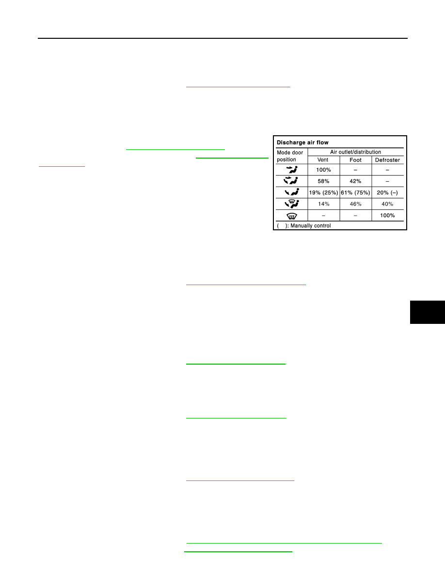
CHECKING DISCHARGE AIR
1.
Press MODE switch and DEF switch.
2.
Each position indicator should change shape.
3.
Confirm that discharge air comes out according to the air distri-
bution table. Refer to
.
If NG, go to trouble diagnosis procedure for
If OK, continue the check.
NOTE:
Confirm that the compressor clutch is engaged (sound or visual
inspection) and intake door position is at FRE when the D/F or DEF
is selected.
CHECKING INTAKE AIR
1.
Press intake switch. Recirculation indicator should illuminate.
2.
Press intake switch again. Fresh indicator should illuminate.
3.
Listen for intake door position change. (Slight change of blower sound can be heard.)
If NG, go to trouble diagnosis procedure for
ATC-62, "Intake Door Motor Circuit"
If OK, continue the check.
NOTE:
Confirm that the compressor clutch is engaged (sound or visual inspection) and intake door position is at FRE
when the D/F or DEF is selected.
CHECKING TEMPERATURE DECREASE
1.
Press temperature control (DOWN) switch (driver side) until 18
°
C (60
°
F) is displayed.
2.
Check for cold air at discharge air outlets.
If NG, go to trouble diagnosis procedure for
ATC-75, "Insufficient Cooling"
.
If OK, continue the check.
CHECKING TEMPERATURE INCREASE
1.
Press temperature control (UP) switch (driver side) until 32
°
C (90
°
F) is displayed.
2.
Check for hot air at discharge air outlets.
If NG, go to trouble diagnosis procedure for
ATC-82, "Insufficient Heating"
If OK, continue the check.
CHECKING A/C SWITCH
1.
Press AUTO switch and A/C switch.
2.
A/C switch indicator will turn ON.
• Confirm that the compressor clutch engages (sound or visual inspection).
If NG, go to trouble diagnosis procedure for
ATC-69, "Magnet Clutch Circuit"
If OK, continue the check.
CHECKING AUTO MODE
1.
Press AUTO switch and A/C switch.
2.
Display should indicate AUTO.
• Confirm that discharge air and blower speed will depend on ambient, in-vehicle, and set temperatures.
If NG, go to trouble diagnosis procedure for
ATC-52, "Power Supply and Ground Circuit for Auto Amp"
, then if
necessary, trouble diagnosis procedure for
ATC-69, "Magnet Clutch Circuit"
.
SJIA0302E
Нет комментариевНе стесняйтесь поделиться с нами вашим ценным мнением.
Текст