Infiniti FX35 / FX45. Manual — part 114
ATC-52
< SERVICE INFORMATION >
TROUBLE DIAGNOSIS
If all operational checks are OK (symptom cannot be duplicated), go to Incident Simulation Tests in
"How to Perform Efficient Diagnosis for an Electrical Incident"
and perform tests as outlined to simulate driving
conditions environment. If symptom appears, refer to
ATC-32, "How to Perform Trouble Diagnosis for Quick
and perform applicable trouble diagnosis procedures.
Power Supply and Ground Circuit for Auto Amp
INFOID:0000000001328183
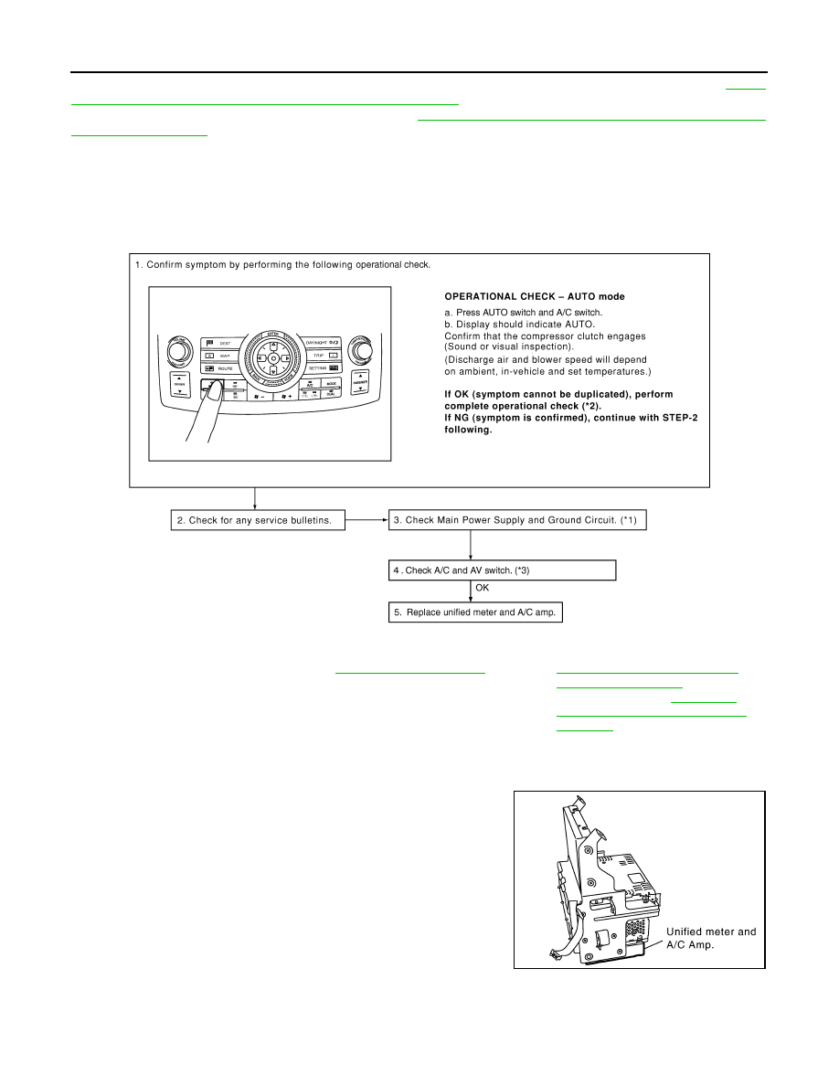
SYMPTOM: A/C system does not activate.
INSPECTION FLOW
COMPONENT DESCRIPTION
Unified Meter and A/C Amp. (Automatic Amplifier)
The unified meter and A/C amp. has a built-in microcomputer which
processes information sent from various sensors needed for air con-
ditioner operation. The air mix door motor, mode door motor, intake
door motor, blower motor and compressor are then controlled.
When the various switches and temperature control switch are oper-
ated, data is input to the unified meter and A/C amp. from the display
control unit using CAN communication.
Self-diagnosis functions are also built into unified meter and A/C
amp. to provide quick check of malfunctions in the auto air condi-
tioner system.
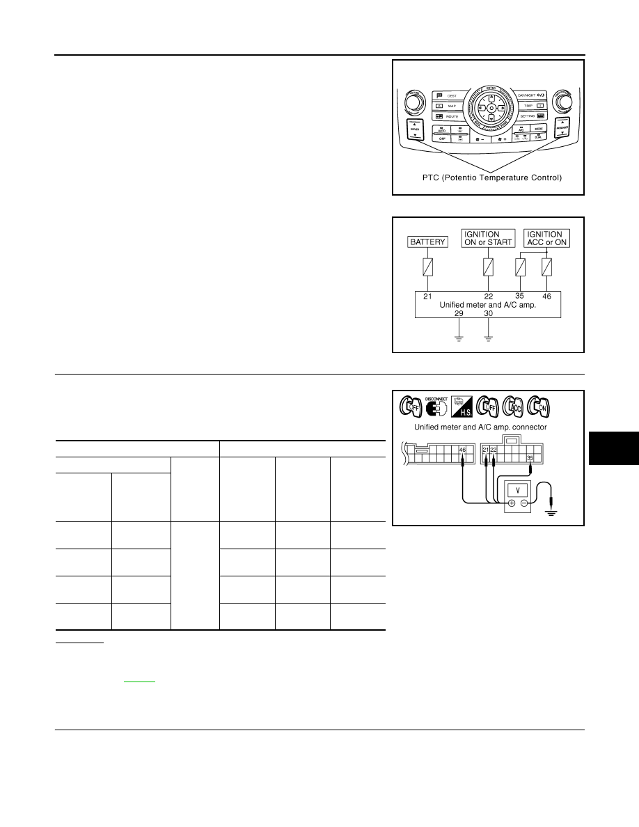
Potentio Temperature Control (PTC)
*1
"DIAGNOSIS PROCEDURE FOR A/
C SYSTEM"
*2
*3
AV-79, "Unable to Operate System
with A/C and AV Switch"
(Without
navigation system) or
able to Operate System with A/C and
AV Switch"
(With navigation system)
SJIA1582E
SJIA1566E
TROUBLE DIAGNOSIS
ATC-53
< SERVICE INFORMATION >
C
D
E
F
G
H
I
K
L
M
A
B
ATC
N
O
P
The PTC is built into the A/C and AV switch. It can be set at an inter-
val of 0.5
°
C (1.0
°
F) in the 18
°
C (60
°
F) to 32
°
C (90
°
F) temperature
range by pressing temperature control switch. The set temperature
is displayed.
DIAGNOSIS PROCEDURE FOR A/C SYSTEM
SYMPTOM: A/C system does not activate.
1.
CHECK POWER SUPPLY CIRCUIT FOR UNIFIED METER AND A/C AMP.
1.
Disconnect unified meter and A/C amp. connector.
2.
Check voltage between unified meter and A/C amp. harness
connector M56 terminals 21, 22 and 35, unified meter and A/C
amp. harness connector M57 terminal 46 and ground.
OK or NG
OK
>> GO TO 2.
NG
>>
Check 10A and 15A fuses [Nos. 6, 10, 11, 12 and 19, located in the fuse block (J/B)]. Refer to
.
• If fuses are OK, check harness for open circuit. Repair or replace if necessary.
• If fuses are NG, check harness for short circuit and replace fuse.
2.
CHECK GROUND CIRCUIT FOR UNIFIED METER AND A/C AMP.
1.
Turn ignition switch OFF.
SJIA1583E
RJIA1983E
Terminals
Ignition switch position
(+)
(
−
)
OFF
ACC
ON
Unified
meter and
A/C amp.
connector
Terminal No.
M56
21
Ground
Battery volt-
age
Battery
voltage
Battery
voltage
M56
22
Approx. 0 V
Approx. 0 V
Battery
voltage
M56
35
Approx. 0 V
Battery
voltage
Battery
voltage
M57
46
Approx. 0 V
Battery
voltage
Battery
voltage
RJIA1984E
ATC-54
< SERVICE INFORMATION >
TROUBLE DIAGNOSIS
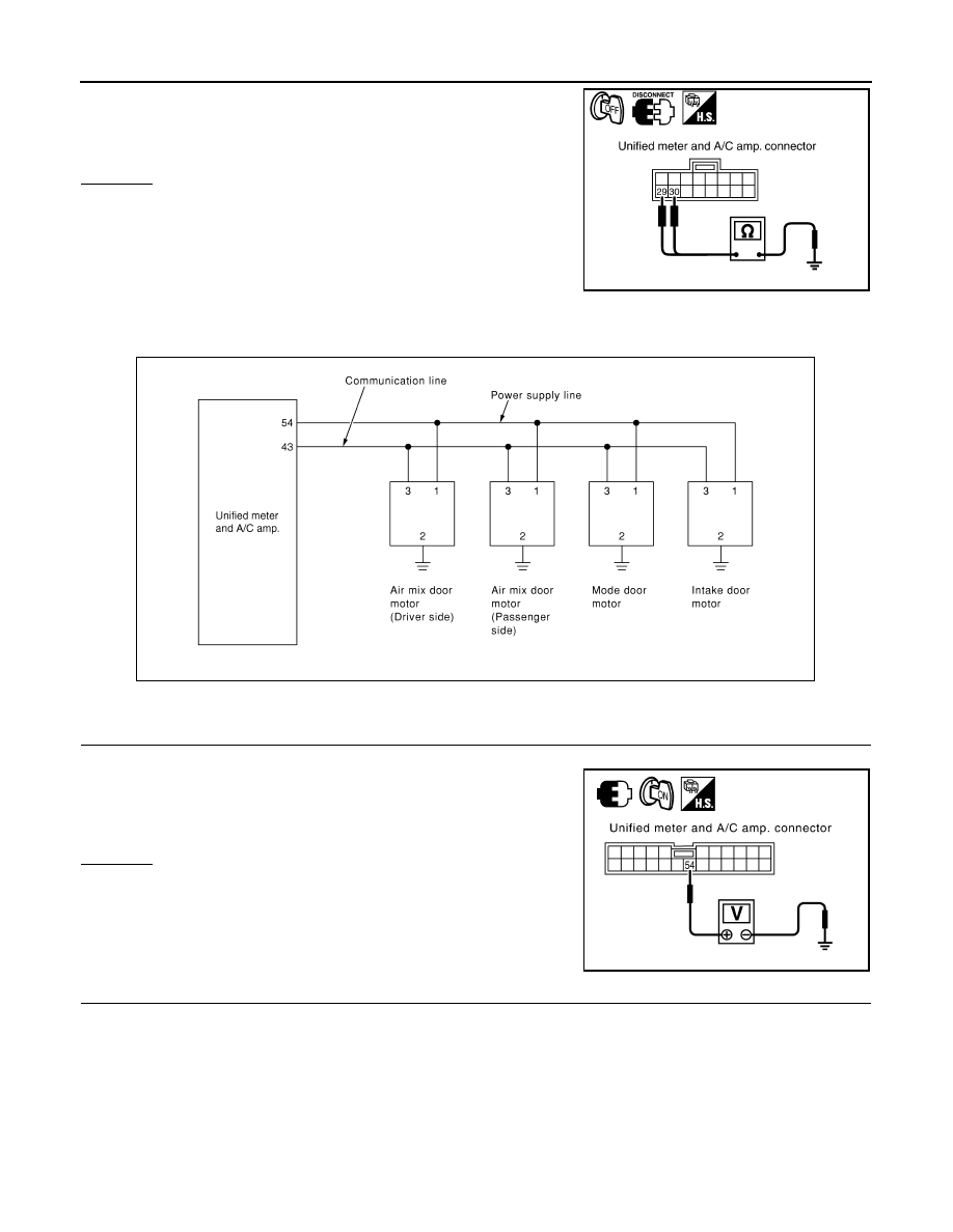
2.
Check continuity between unified meter and A/C amp. harness
connector M56 terminal 29, 30 and ground.
OK or NG
OK
>> Replace unified meter and A/C amp.
NG
>> Repair harness or connector.
LAN System Circuit
INFOID:0000000001328184
SYMPTOM: Mode door motor, intake door motor and/or air mix door motor(s) does not operate normally.
DIAGNOSIS PROCEDURE FOR LAN CIRCUIT
1.
CHECK POWER SUPPLY FOR UNIFIED METER AND A/C AMP.
1.
Turn ignition switch ON.
2.
Check voltage between unified meter and A/C amp. harness
connector M57 terminal 54 and ground.
OK or NG
OK
>> GO TO 2.
NG
>> Replace unified meter and A/C amp.
2.
CHECK SIGNAL FOR UNIFIED METER AND A/C AMP.
29, 30 – Ground
: Continuity should exist.
RJIA1985E
RJIA1775E
54 – Ground
: Battery voltage
RJIA1986E
TROUBLE DIAGNOSIS
ATC-55
< SERVICE INFORMATION >
C
D
E
F
G
H
I
K
L
M
A
B
ATC
N
O
P
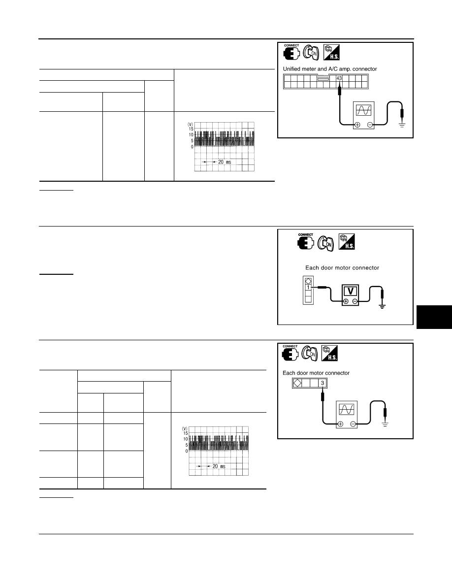
Confirm A/C LAN signal between unified meter and A/C amp. har-
ness connector M57 terminal 43 and ground using an oscilloscope.
OK or NG
OK
>> GO TO 3.
NG
>> Replace unified meter and A/C amp.
3.
CHECK POWER SUPPLY FOR EACH DOOR MOTOR
Check voltage between each door motor harness connector terminal
1 and ground.
OK or NG
OK
>> GO TO 4.
NG
>> Repair harness or connector.
4.
CHECK SIGNAL FOR EACH DOOR MOTOR
Confirm A/C LAN signal between each door motor harness connec-
tor terminal 3 and ground using an oscilloscope.
OK or NG
OK
>> GO TO 5.
NG
>> Repair harness or connector.
5.
CHECK MOTOR GROUND CIRCUIT
1.
Turn ignition switch OFF.
2.
Disconnect each door motor connector.
Terminals
Voltage
(+)
(
−
)
Unified meter and A/
C amp. connector
Terminal No.
M57
43
Ground
RJIA1987E
SJIA1453J
1 – Ground
: Battery voltage
RJIA1988E
Door motor
Terminals
Voltage
(+)
(
−
)
Con-
nector
Terminal
No.
Mode
M258
3
Ground
Air mix
(Driver
side)
M252
3
Air mix
(Passen-
ger side)
M257
3
Intake
M253
3
RJIA1989E
SJIA1453J
Нет комментариевНе стесняйтесь поделиться с нами вашим ценным мнением.
Текст