Infiniti FX35 / FX45. Manual — part 709
FUEL LEVEL SENSOR UNIT, FUEL FILTER AND FUEL PUMP ASSEMBLY
FL-5
< SERVICE INFORMATION >
C
D
E
F
G
H
I
J
K
L
M
A
FL
N
P
O
2.
Release the fuel pressure from the fuel lines. Refer to
(VQ35DE) or
3.
Open fuel filler lid.
4.
Open filler cap and release the pressure inside fuel tank.
5.
Remove rear seat cushion. Refer to
SE-95, "Removal and Installation"
.
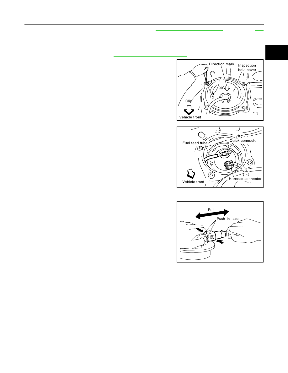
6.
Peel off floor carpet, then remove inspection hole cover for main
and sub fuel level sensor units by turning clips clockwise by 90
degrees.
7.
Disconnect harness connector and fuel feed tube.
Disconnect quick connector as follows:
• Hold the sides of connector, push in tabs and pull out tube.
• If quick connector sticks to tube of main fuel level sensor unit,
push and pull quick connector several times until they start to
move.Then disconnect them by pulling.
CAUTION:
PBIC1576E
PBIC1577E
SFE562A
FL-6
< SERVICE INFORMATION >
FUEL LEVEL SENSOR UNIT, FUEL FILTER AND FUEL PUMP ASSEMBLY
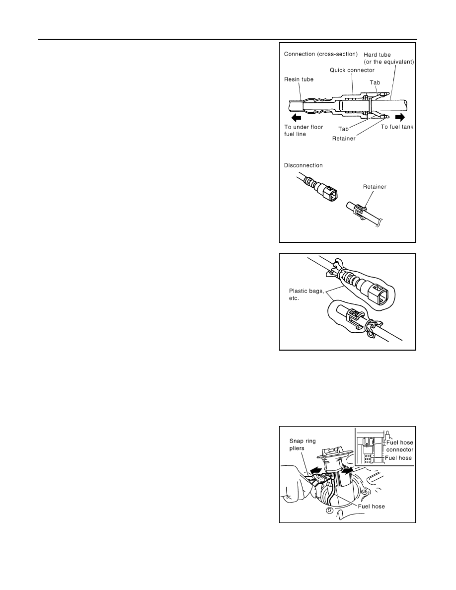
• Quick connector can be disconnected when the tabs are
completely depressed. Do not twist it more than neces-
sary.
• Do not use any tools to disconnected quick connector.
• Keep resin tube away from heat. Be especially careful
when welding near the resin tube.
• Prevent acid liquid such as battery electrolyte, etc. from
getting on resin tube.
• Do not bend or twist resin tube during installation and
disconnection.
• Do not remove the remaining retainer on hard tube (or
the equivalent) except when resin tube or retainer is
replaced.
• When resin tube or hard tube (or the equivalent) is
replaced, also replace retainer with new one.
• To keep the connecting portion clean and to avoid dam-
age and foreign materials, cover them completely with
plastic bags or something similar.
8.
Remove main fuel level sensor unit, fuel filter and fuel pump assembly, and sub fuel level sensor unit as
follows:
CAUTION:
• Do not bend float arm during removal.
• Avoid impacts such as falling when handling components.
a.
Removal of main fuel level sensor unit, fuel filter and fuel pump assembly:
i.
Remove retainer.
ii.
Raise main fuel level sensor unit, fuel filter and fuel pump
assembly, and using snap ring pliers, remove fuel hose connec-
tor.
CAUTION:
Be careful not to damage fuel hose connector by expanding
them excessively.
b.
Removal of sub fuel level sensor unit:
i.
Remove retainer.
ii.
Raise and release sub fuel level sensor unit to remove.
INSTALLATION
Note to the following, and install in the reverse order of removal.
Main and Sub Fuel Level Sensor Unit
Retainer color: White
SBIA0504E
PBIC0163E
PBIC1578E
FUEL LEVEL SENSOR UNIT, FUEL FILTER AND FUEL PUMP ASSEMBLY
FL-7
< SERVICE INFORMATION >
C
D
E
F
G
H
I
J
K
L
M
A
FL
N
P
O
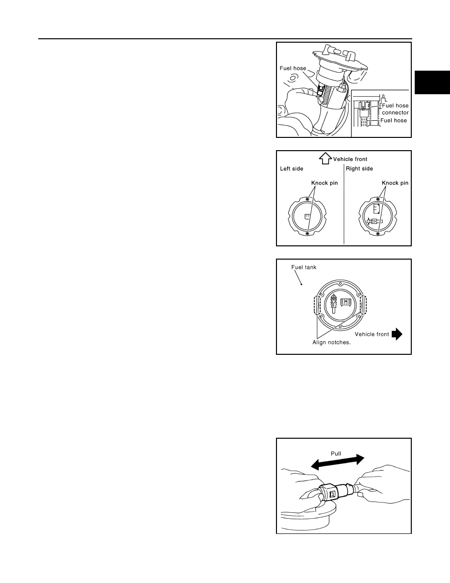
• When installing fuel hose connector insert them fully until a click
sound of full stopper engagement is heard.
• Face main and sub fuel level sensor units as shown in the figure,
and install them with the knock pin on back aligned with pin hole on
fuel tank.
• Install retainer so that its notch becomes parallel with the notch on
fuel tank.
• Tighten retainer mounting bolts evenly.
Quick Connector
Connect quick connector as follows:
1.
Check the connection for damage or any foreign materials.
2.
Align the connector with the tube, then insert the connector straight into the tube until a click sound is
heard.
3.
After connecting, make sure that the connection is secure by following method.
• Pull the tube and the connector to make sure they are securely
connected.
• Visually confirm that the two retainer tabs are connected to the
connector.
INSPECTION AFTER INSTALLATION
Use the following procedure to check for fuel leaks.
PBIC1579E
PBIC1065E
PBIC1652E
PBIC1653E
FL-8
< SERVICE INFORMATION >
FUEL LEVEL SENSOR UNIT, FUEL FILTER AND FUEL PUMP ASSEMBLY
1.
Turn ignition switch “ON” (with engine stopped), then check connections for leaks by applying fuel pres-
sure to fuel piping.
2.
Start engine and let it idle and make sure there are no fuel leaks at the fuel system connections.
Component
INFOID:0000000001327108
Disassembly and Assembly
INFOID:0000000001327109
CAUTION:
Sub fuel level sensor unit cannot be disassembled and should be replaced as a unit.
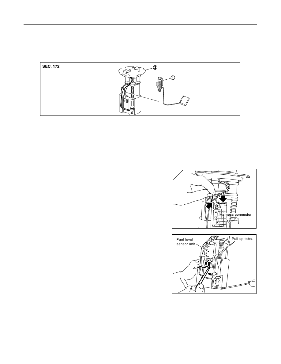
DISASSEMBLY
Remove fuel level sensor unit as follows.
1.
Disconnect harness connector.
• Hold connector by fingers and pull it out, because there is no
stopper release tab.
2.
Using suitable tool, pull up tabs points as shown in the figure
(two points) to release the lock.
CAUTION:
Be careful not to damage it.
1.
Fuel level sensor unit
2.
Fuel filter and fuel pump assembly
PBIC1081E
PBIC1078E
PBIC1654E
Нет комментариевНе стесняйтесь поделиться с нами вашим ценным мнением.
Текст